Hanging lug, backlight module and display device

A backlight module and backplane technology, applied in the field of backlight modules, display devices, and mounting ears, can solve problems such as the detachment of the mounting ear backplane and the detachment of the optical film, and achieve the effects of improving assembly reliability and increasing clamping strength.

Pending Publication Date: 2020-08-07
BOE TECH GRP CO LTD +1
View PDF0 Cites 3 Cited by
  • Summary
  • Abstract
  • Description
  • Claims
  • Application Information

AI Technical Summary

Problems solved by technology

[0004] The invention provides a hanging ear, a backlight module and a display device to solve the problems that the hanging ear is easy to detach from the backplane of the backlight module, and the optical film of the backlight module is easy to detach from the hanging ear

Method used


Image

  • Hanging lug, backlight module and display device
  • Hanging lug, backlight module and display device
  • Hanging lug, backlight module and display device

Examples


Embodiment 1

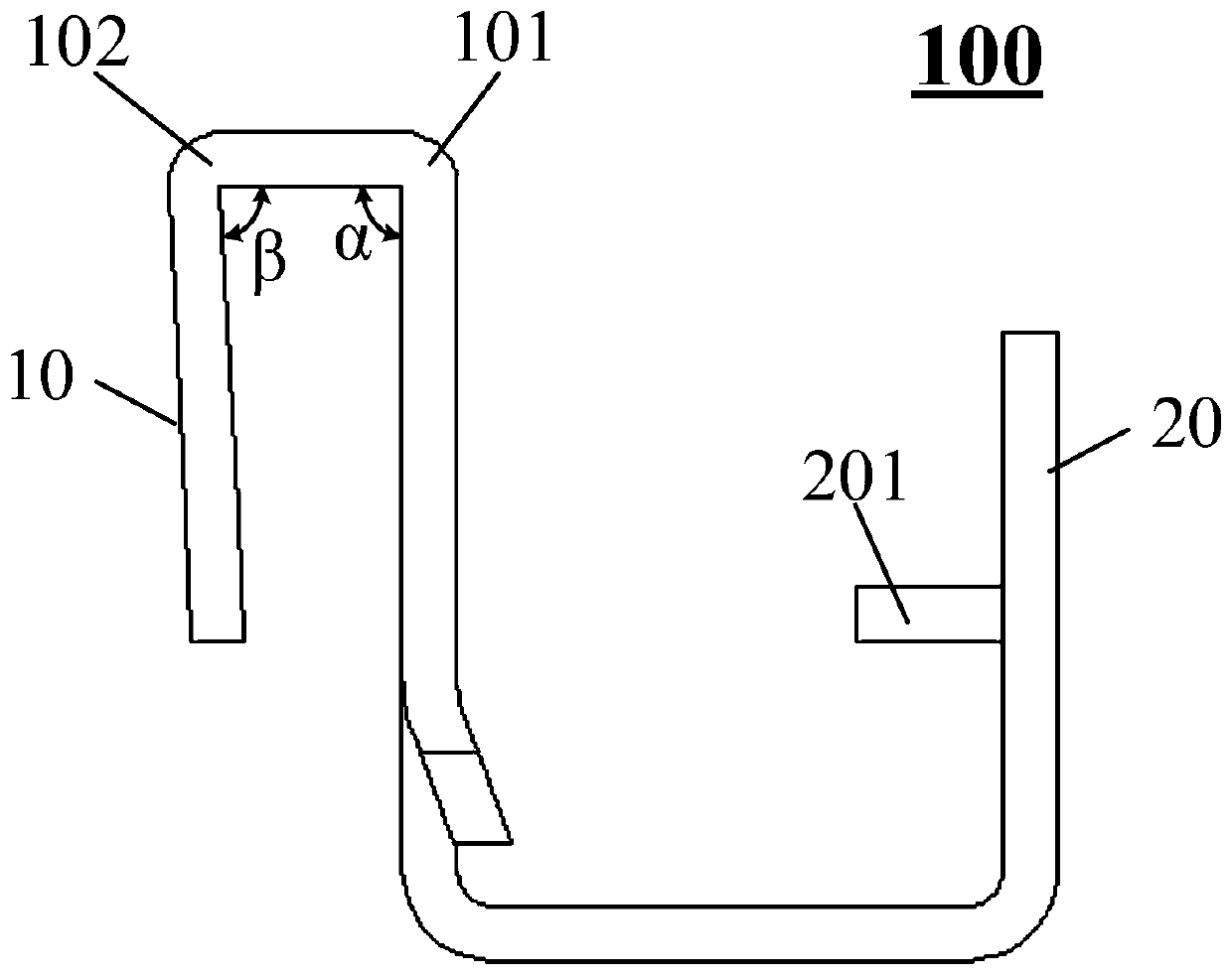
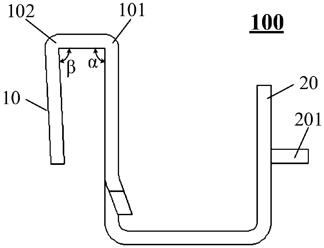
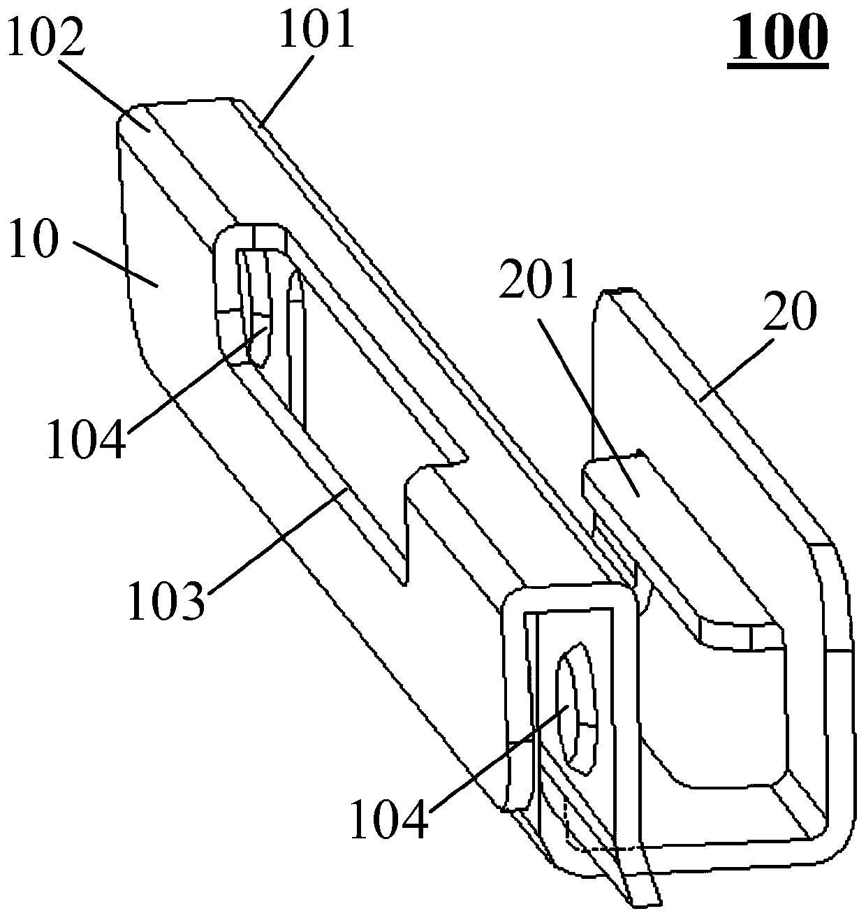
[0030] figure 1 It shows a side view of a hanging ear according to Embodiment 1 of the present invention, refer to figure 1 , the hanging ear 100 includes a first fixing structure 10 for clamping the backplane of the backlight module, and a second fixing structure 20 for fixing the optical film of the backlight module, the first fixing structure 10 and The second fixing structures 20 are U-shaped, one end of the first fixing structure 10 is connected to one end of the second fixing structure 20, and the opening of the first fixing structure 10 is connected to the second fixing structure. The opening direction of 20 is opposite, that is to say, one of the first fixing structure 10 and the second fixing structure 20 is in an inverted U shape, and the other is connected in a positive U shape, such as figure 1 shown. The first fixing structure 10 includes a first bending portion 101 close to the second fixing structure 20, and a second bending portion 102 connected to the first ...

Embodiment 2

[0046] Figure 5 A partial schematic diagram of a backlight module according to Embodiment 2 of the present invention is shown, refer to Figure 5 , the backlight module includes a backplane 300 , an optical film 400 and the above-mentioned hanging ears 100 .

[0047] In practical applications, the backlight module also includes conventional structures such as the light guide plate 500 , which will not be described in detail here.

[0048] Optionally, refer to Figure 5 , the back panel 300 includes a bottom panel 301 and a side panel 302 bent relative to the bottom panel 301 , and the first fixing structure 10 of the hanging ear clamps the side panel 302 .

[0049] Wherein, since the bending angle of at least one bending portion of the first fixing structure 10 of the hanging ear is designed to be an acute angle, the clamping force of the U-shaped first fixing structure 10 on the backlight module backplane 300 can be improved, so that the hanging ear It is not easy to sepa...

Embodiment 3

[0067] The embodiment of the invention also discloses a display device, including the above-mentioned backlight module.

[0068] Optionally, the display device may be a television, which is not specifically limited in this embodiment of the present invention.

[0069]In the embodiment of the present invention, the hanging ear in the backlight module includes a first fixing structure and a second fixing structure, both of the first fixing structure and the second fixing structure are U-shaped, and one end of the first fixing structure is connected with the second fixing structure One end is connected, and the opening of the first fixing structure is opposite to the opening of the second fixing structure, the first fixing structure clamps the back plate, and the second fixing structure fixes the optical film. Wherein, the first fixing structure includes a first bending portion close to the second fixing structure, and a second bending portion connected to the first bending porti...


PUM


Abstract

The invention provides a hanging lug, a backlight module and a display device, and relates to the technical field of display. The hanging lug comprises a first fixing structure used for clamping the backboard and a second fixing structure used for fixing the optical film, the first fixing structure and the second fixing structure are both U-shaped, one end of the first fixing structure is connected with one end of the second fixing structure, and the opening directions of the two fixing structures are opposite; the first fixing structure comprises a first bent part close to the second fixing structure and a second bent part connected with the first bent part, and the bent angle of the first bent part and/or the bent angle of the second bent part are/is an acute angle. And a limiting structure is arranged on the second fixing structure. According to the invention, the bending angle of at least one bending part of the first fixing structure is set to be the acute angle, so that the clamping force of the hanging lug on the backboard can be improved, the hanging lug is not easy to separate from the backboard, and the assembly reliability is improved. Besides, when the optical film is fixed by the second fixing structure, the optical film can be limited by the limiting structure, so that the optical film is not easy to separate from the suspension loop, and the assembly reliabilityis improved.

Description

technical field [0001] The invention relates to the field of display technology, in particular to a hanging ear, a backlight module and a display device. Background technique [0002] Various optical components in the backlight module play a very important role in the display effect. Therefore, it is necessary to ensure the reliability of each optical component after assembly, especially the optical film therein. At present, the optical film in the backlight module is usually connected and fixed to the backplane of the backlight module through hanging lugs, wherein one end of the hanging lug clamps the backplane, and the other end of the hanging lug fixes the optical film. [0003] However, in practical applications, when performing tests such as mechanical vibration and drop, as well as during the subsequent use of the display device, the mounting lugs are easy to detach from the backplane, and the optical diaphragm is also easily detached from the mounting lugs, so that fi...

Claims


Application Information

Patent Timeline
Patent Type & Authority Applications(China)
IPC IPC(8): G09F9/00
CPCG09F9/00
Inventor 高林海
Owner BOE TECH GRP CO LTD
Why Eureka
Try Eureka