Connector

A technology of connectors and connecting parts, which is applied in the direction of connection, parts and contact parts of connecting devices, etc., can solve the problems of occupation, large size of connectors, and large space.

Active Publication Date: 2020-08-07
DONGGUAN LUXSHARE TECH CO LTD
View PDF8 Cites 1 Cited by
  • Summary
  • Abstract
  • Description
  • Claims
  • Application Information

AI Technical Summary

Problems solved by technology

[0003] The bending part is usually bent into a semi-circular arc shape, and the contact terminals will protrude to one side, which takes up a large space, resulting in a small number of contact terminals arranged

Method used


Image

  • Connector
  • Connector
  • Connector

Examples


Embodiment 1

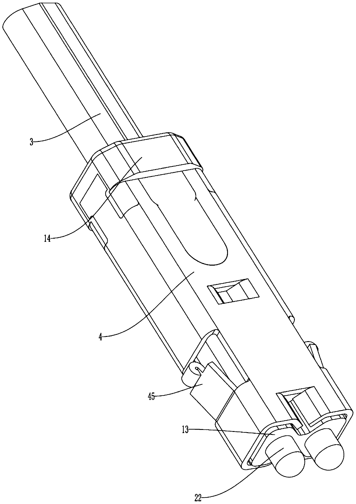
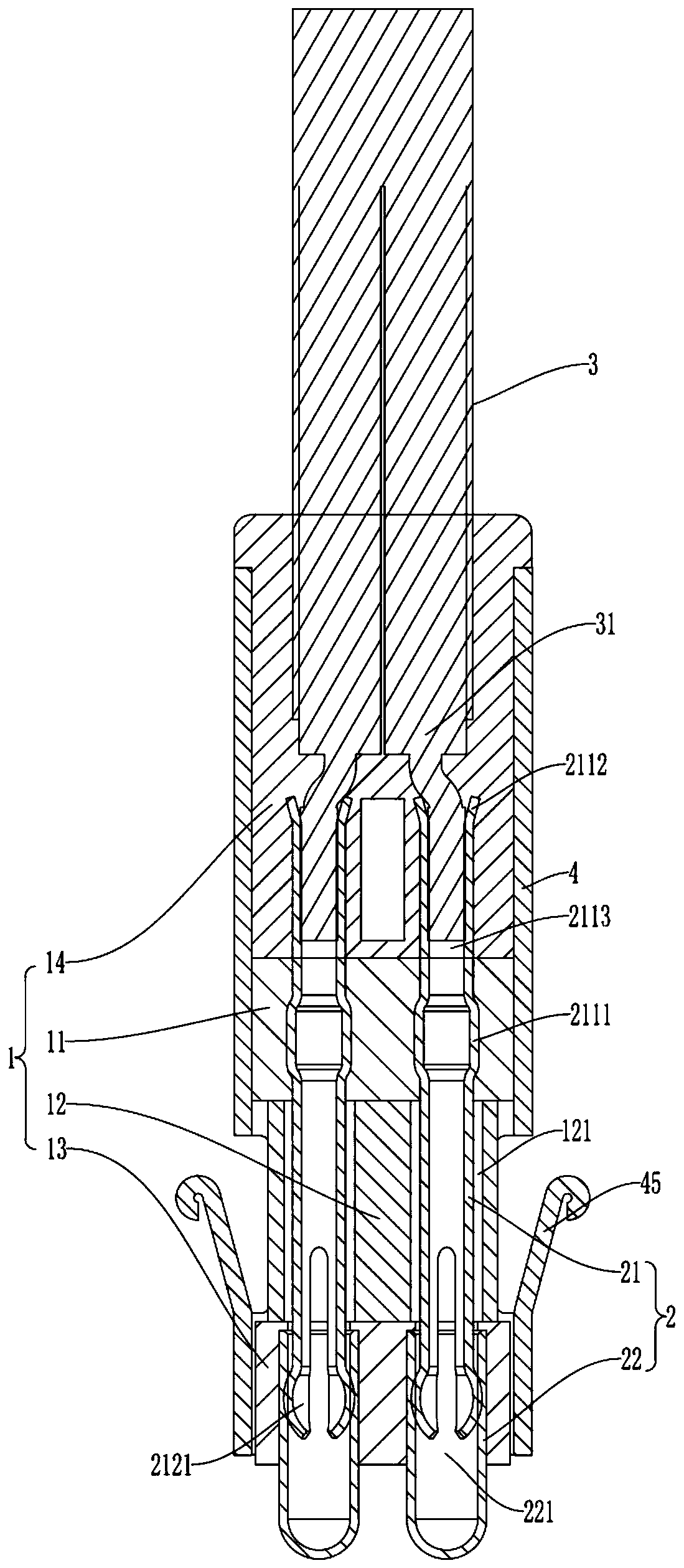
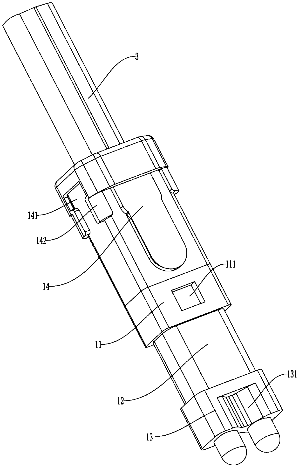
[0045] Such as Figure 1-3As shown, the connector includes an insulating body assembly 1 and a plurality of terminal assemblies 2 arranged side by side. Preferably, the number of terminal assemblies 2 in this embodiment is two. The terminal assembly 2 includes a connecting terminal 21 and a contact terminal 22. The connecting terminal 21 is arranged in the insulating body assembly 1, the tail end of the contact terminal 22 is arranged in the insulating body assembly 1, and the front end is exposed to the insulating body assembly 1. The contact terminal 22 The tail portion is provided with a receiving hole 221 , the contact terminal 22 is sleeved on the front end of the connecting terminal 21 , and the length of the sleeve is adjustable, and the front end of the connecting terminal 21 elastically contacts with the inner wall of the receiving hole 221 .

[0046] The front end of the connection terminal 21 is in elastic contact with the inner wall of the receiving hole 221, so t...

Embodiment 2

[0056] This embodiment provides a connector whose structure is basically the same as that of Embodiment 1, except for the structure of the connecting terminal.

[0057] Such as Figure 7 As shown, the connection terminal 21 is in the shape of a strip, and is bent at the part located in the first insulating block 11, forming a bent portion 2114, which is located in the first insulating block 11, so as to avoid the connection terminal 21 Dislocation movement occurs with the first insulating block 11 . The front end of the connecting terminal 21 is punched to form an elliptical through hole, and the major axis of the ellipse is located in the longitudinal direction of the connecting terminal 21 . Parts of the connecting terminal 21 located on both sides of the through hole protrude outward to form contact protrusions 2121 . When the front end of the connection terminal 21 extends into the contact terminal 22, the two contact protrusions 2121 will be drawn inward, and the two co...

Embodiment 3

[0059] This embodiment provides a connector whose structure is basically the same as that of Embodiment 1, except for the structure of the connecting terminal.

[0060] Such as Figure 8 As shown, the connection terminal 21 is in the shape of a strip, and is bent at the part located in the first insulating block 11, forming a bent portion 2114, which is located in the first insulating block 11, so as to avoid the connection terminal 21 Dislocation movement occurs with the first insulating block 11 .

[0061] In this embodiment, the elastic arms are two symmetrically arranged elastic rods 213 , and the contact protrusions 2121 are arranged outside the front ends of the elastic rods 213 . When the front end of the connection terminal 21 is inserted into the contact terminal 22 , the two contact protrusions 2121 abut against the inner wall of the contact terminal 22 , and the two elastic rods 213 are deformed to have a certain elastic force. The elastic rod 213 can ensure that ...


PUM


Abstract

The invention relates to the technical field of connectors and discloses a connector which comprises an insulating body assembly and a plurality of terminal assemblies arranged side by side, each terminal assembly comprises a connecting terminal and a contact terminal; the connecting terminals are arranged in the insulating body assembly, the front ends of the contact terminals are exposed out ofthe insulating body assembly, tail parts of the contact terminals are provided with accommodating holes, the contact terminals sleeve the front ends of the connecting terminals, the sleeving length isadjustable, and the front ends of the connecting terminals are in elastic contact with inner walls of the accommodating holes. The contact terminals are contracted in a manner of moving towards the direction of the connecting terminals and are not contracted in a bending manner by elastic deformation. Therefore, the part exposed out of the insulating body assembly does not need to be bent, the space occupied by the contact terminals can be reduced, more terminal assemblies can be arranged in the limited space of the connector without increasing the volume of the connector, and the requirementof miniaturization development of the connector is met.

Description

technical field [0001] The invention relates to the technical field of connectors, in particular to a connector. Background technique [0002] At present, there are connection methods such as crimping fisheye, welding and elastic contact with the PCB connection cable. The way of the elastic contact is that the part of the contact terminal exposed to the insulating body is bent and arranged. The bent part abuts against the PCB to be connected to the PCB. [0003] The bending part is usually bent into a semi-circular arc shape, and the contact terminals will protrude to one side, which takes up a large space, resulting in a small number of contact terminals arranged in the connector. If more signals need to be transmitted, you need to set More contact terminals will increase the volume of the connector, which does not meet the development requirements of the miniaturization of the connector. [0004] Therefore, there is an urgent need for a connector to solve the above tech...

Claims


Application Information

Patent Timeline
IPC IPC(8): H01R13/05H01R13/40H01R13/502
CPCH01R13/40H01R13/502H01R13/055H01R13/052H01R13/2407H01R13/6315
Inventor 宋涛曾晨辉王开德
Owner DONGGUAN LUXSHARE TECH CO LTD
Why Eureka
Try Eureka