
A method and laser system for realizing stable output of laser

A stable output, laser technology, applied in the field of lasers, can solve the problems of deterioration of processing quality, reduction of processing accuracy, beam deviation, etc., to achieve the effects of high power stability, high-quality product performance, and high environmental reliability

Active Publication Date: 2021-07-27
XI'AN INST OF OPTICS & FINE MECHANICS - CHINESE ACAD OF SCI
View PDF5 Cites 0 Cited by
  • Summary
  • Abstract
  • Description
  • Claims
  • Application Information

AI Technical Summary

Problems solved by technology

[0004] For example, in the field of laser micromachining, the precision of micromachining can reach 1.5um, and the smallest etched microstructure size is tens of microns. Such high-precision material processing requires that the laser beam as a light knife remain almost unchanged during the working process. The transmission characteristics, its small jitter will cause the beam focused on the material to seriously deviate or lose focus, resulting in deterioration of processing quality and reduction of processing accuracy

Method used


Image

  • A method and laser system for realizing stable output of laser
  • A method and laser system for realizing stable output of laser
  • A method and laser system for realizing stable output of laser

Examples


Embodiment 1

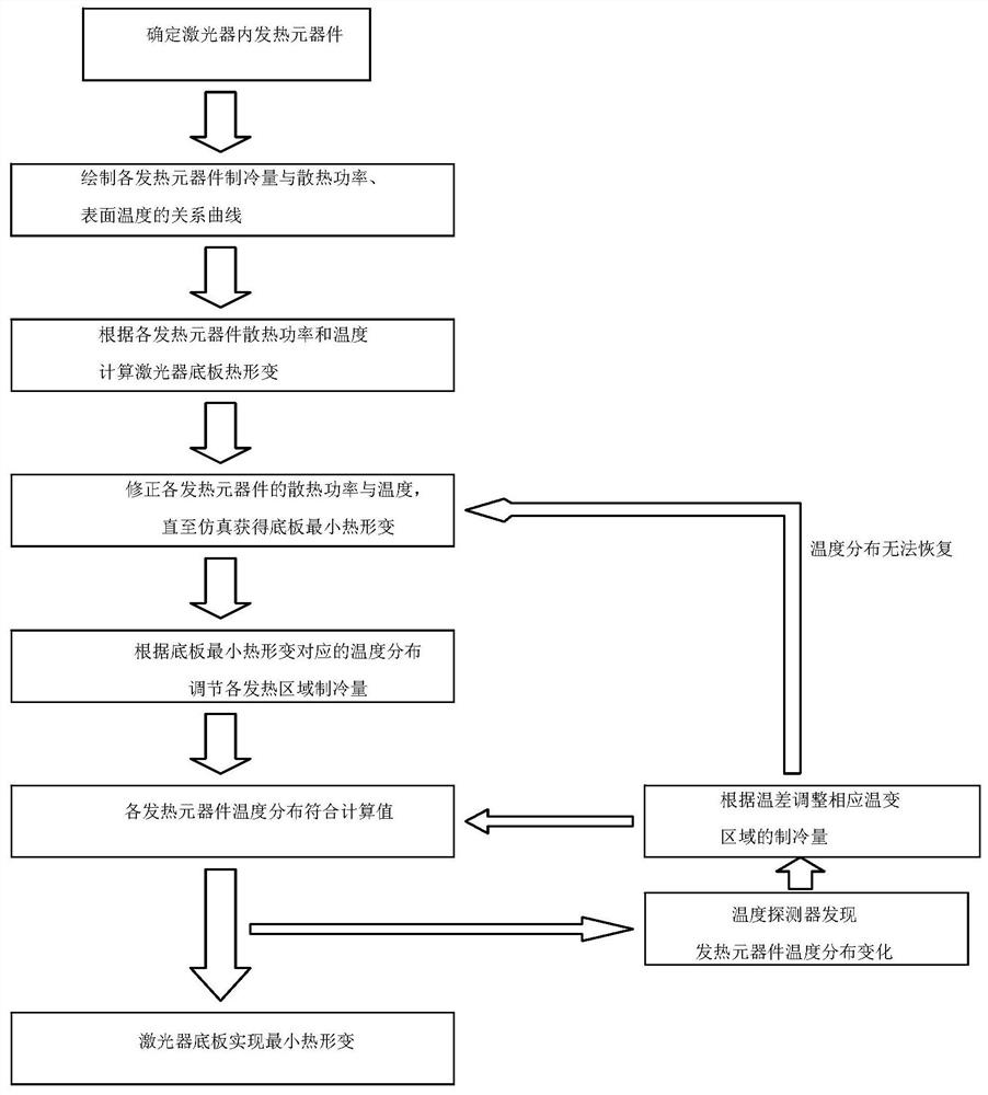
[0080] This embodiment provides a solution in which the refrigeration component is water-cooled to further describe the present invention in detail.

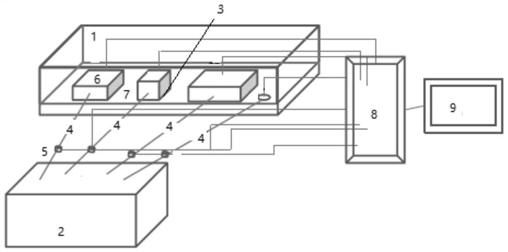
[0081] Step 1: Determine the heating components inside the main body of the laser; the heating components include the LD pump module, the laser crystal module, the electro-optic or acousto-optic modulator module, and the circuit control modules installed on the laser base plate;

[0082] Step 2: Set a water cooling plate and corresponding flow valve and heat flow meter on each heating element, and unify the water temperature setting of the water cooler;

[0083] Step 3: make each heating element work at rated power, and obtain the cooling power of the cooling component corresponding to each heating element;

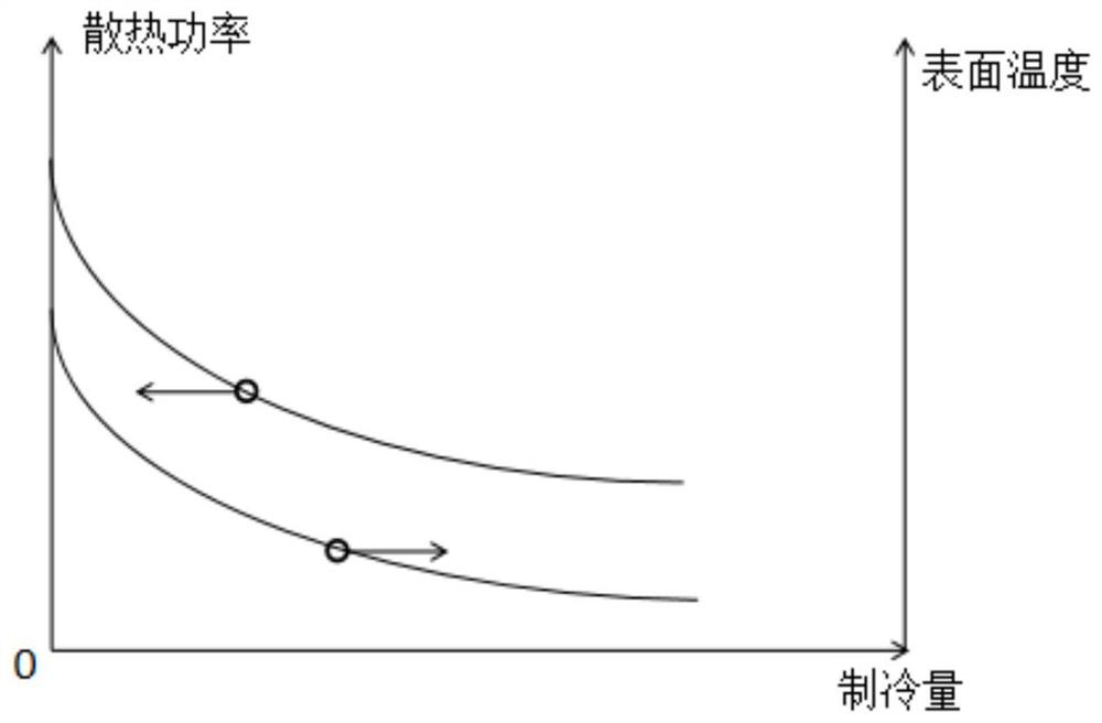
[0084] Step 4: Change the flow setting value of each flow valve respectively, and measure the relationship curve between the cooling water flow value of each heating element and the cooling power and surface temperature of ...

Embodiment 2

[0100] This embodiment provides a solution in which the refrigeration component is an electric refrigeration to further describe the present invention in detail.

[0101] Step 1: Determine the heating components inside the main body of the laser; the heating components include LD pump modules, laser crystal modules, electro-optic or acousto-optic modulator modules, and various circuit control modules installed on the laser base plate.

[0102] Step 2: Set a semiconductor cooling chip on each heating element, and set a thermostat to control the semiconductor cooling chip;

[0103] Step 3: make each heating element work at rated power, and obtain the heat dissipation power of the semiconductor refrigeration sheet corresponding to each heating element;

[0104] Step 4: Change the cooling capacity of each semiconductor refrigerating sheet respectively, and measure the relationship curve between the refrigerating capacity of each heating element and the heat dissipation power and s...


PUM


Abstract

The invention discloses a method for realizing stable output of a laser and a laser system. The invention measures and analyzes the heating conditions of each heating element inside the laser, simulates the cooling capacity that needs to be maintained in the best working state of the laser, detects the temperature of each heating element inside the laser in real time, and compares the detected Real-time temperature and the temperature in the optimized cooling scheme, and timely correct the cooling capacity of each heating component inside the laser in the cooling scheme, so as to achieve the goal of laser optical-mechanical thermal balance starting from the global area. The laser has strong environmental adaptability, good output beam quality, and excellent product performance for long-term working stability.

Description

technical field [0001] The invention belongs to the technical field of lasers, and in particular relates to a method and a laser system for realizing stable output of a laser. Background technique [0002] Among all the parameters of the laser, the output power and stability of the laser are the most basic technical indicators of the output characteristics of the laser, and are also the most important index parameters, which directly affect the quality and efficiency of processing. [0003] The main factors affecting the laser output power and its stability include working current, working voltage, working temperature and many other factors. Among them, the working temperature not only affects the stability of the laser output power, but also affects the laser pointing stability, beam quality and other key parameters , and the application requirements of these parameters in fields such as laser processing are extremely strict, such as the pointing stability of the laser, the...

Claims


Application Information

Patent Timeline
Patent Type & Authority Patents(China)
IPC IPC(8): H01S3/13H01S3/131H01S3/04
CPCH01S3/0405H01S3/0407H01S3/13H01S3/1317
Inventor 杨直赵卫杨小君王屹山李强龙
Owner XI'AN INST OF OPTICS & FINE MECHANICS - CHINESE ACAD OF SCI
Learn More