Measurement system for optical element transmittance and reflectance based on acousto-optic modulation

An optical device, transmittance and reflectivity technology, applied in the field of laser measurement, can solve the problem of insufficient transmittance and reflectivity measurement accuracy of optical devices, and achieve the effects of enhancing readability, improving measurement accuracy, and reducing power fluctuations

Inactive Publication Date: 2015-12-09
XIDIAN UNIV
View PDF7 Cites 12 Cited by
  • Summary
  • Abstract
  • Description
  • Claims
  • Application Information

AI Technical Summary

Problems solved by technology

[0004] The purpose of the present invention is to overcome the deficiencies in the prior art above, and propose a measurement system for the transmittance and reflectance of optical devices based on acousto-optic modulation, which is used to solve the problem that the measurement accuracy of the existing measurement system for the transmittance and reflectance of optical devices is not high enough technical issues

Method used


Image

  • Measurement system for optical element transmittance and reflectance based on acousto-optic modulation
  • Measurement system for optical element transmittance and reflectance based on acousto-optic modulation
  • Measurement system for optical element transmittance and reflectance based on acousto-optic modulation

Examples


Embodiment Construction

[0023] In order to make the purpose of the present invention, the technical problem to be solved and the technical solution clearer, the present invention will be further described in detail below in conjunction with the accompanying drawings.

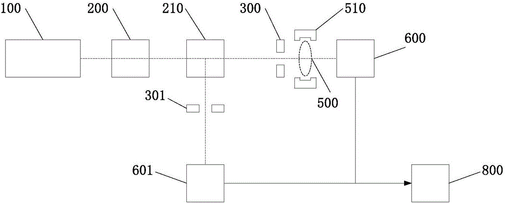
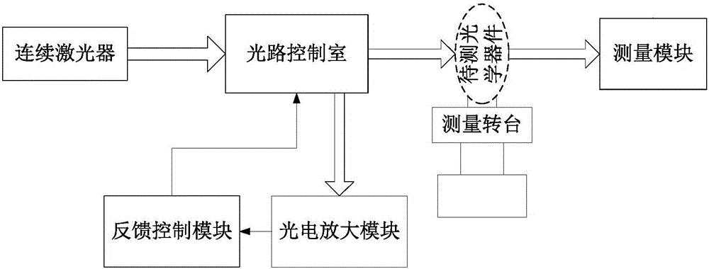
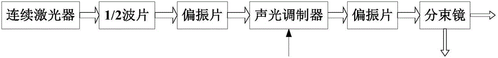
[0024] Figure 2-Figure 6 The thick white arrows in the middle represent laser signals, and the narrow black arrows represent electrical signals.

[0025] refer to figure 2 , the present invention includes a continuous laser, an optical path control room, a measuring turntable, a measuring module, a photoelectric amplification module and a feedback control module, wherein:

[0026] Continuous laser According to the different requirements of the optical device to be tested for the light source, select the corresponding continuous laser as the light source of the measurement system, and fix it on the optical platform to ensure the stability of the optical path of the output laser signal;

[0027] The optical path control room is verti...


PUM


Abstract

The invention realizes a measurement system for optical element transmittance and reflectance based on acousto-optic modulation, which is mainly used for solving the problem that the prior art is not high in measurement accuracy. The measurement system disclosed by the invention comprises a continuous laser, an optical path control chamber, an photoelectric amplification module, a feedback control module, a measurement rotary table and a parameter measurement module; the laser outputs laser with power to be stabilized; the laser outputted by the laser is radiated to a detector in a perpendicular manner after passing through the optical path control chamber to generate a current signal which is amplified by the photoelectric amplification module into a voltage signal; the feedback control module processes the voltage signal to obtain an feedback signal in order to control an acousto-optic demodulation driving device to adjust an acousto-optic demodulator to stabilize the laser power; the highly stable laser enters the optical member to be detected; and the laser power is obtained through measuring transmittance and reflectance of the optical member to be measured to calculate the reflectance and transmittance of the optical member to be measured. The invention is high in measurement accuracy and easy in operation.

Description

technical field [0001] The invention belongs to the technical field of laser measurement. It relates to a system that modulates the power of a laser light source through acousto-optic modulation, so that the output laser power has high stability, and is used for accurate measurement of the transmittance and reflectance of optical devices. Background technique [0002] The transmittance and reflectance of optical devices is an important parameter for evaluating optical devices. Usually, the ratio of the luminous flux after passing through the optical device to the incident luminous flux is used to characterize the transmittance of the object; the ratio of the amount of light that can be reflected by the surface of the object to the amount of light it receives is used to characterize the reflectance of the object. In the design process of various optical systems in practical applications, because the system has different requirements for the transmittance and reflectance of o...

Claims


Application Information

Patent Timeline
Patent Type & Authority Applications(China)
IPC IPC(8): G01M11/02
Inventor 邵晓鹏高苗李晨旭闫庭辉赵大虎温少华
Owner XIDIAN UNIV
Why Eureka
Try Eureka