Shift register and driving circuit of LCD using the same

a technology of shift register and driver circuit, which is applied in the direction of digital storage, instruments, computing, etc., can solve the problem of instantaneous consumption of a large amount of power, and achieve the effect of reducing instantaneous power fluctuation

Inactive Publication Date: 2009-06-23
SAMSUNG DISPLAY CO LTD
View PDF7 Cites 10 Cited by
  • Summary
  • Abstract
  • Description
  • Claims
  • Application Information

AI Technical Summary

Benefits of technology

[0011]Therefore, it is an object of the present invention to reduce instantaneous power fluctuation caused during an operation of shift register and EMI by adjusting the timing of operation of each of memory devices arranged in line in the shift register.
[0012]It is another object of the present invention to check in advance the shift state of data being applied to a shift register that is configured as a matrix so as to process predetermined bits of data, and reduce cases of operation of shift register, to thereby reduce power consumption and EMI caused by a large number of shift registers operating at the same time.
[0013]It is still another object of the present invention to improve configuration of a shift register which constitutes components for driving a flat panel display in such a manner that a plurality of shift registers are prevented from being operated at the same time, to thereby reduce power consumption and EMI.

Problems solved by technology

This consumes a large amount of power instantaneously while producing EMI.

Method used


Image

  • Shift register and driving circuit of LCD using the same
  • Shift register and driving circuit of LCD using the same
  • Shift register and driving circuit of LCD using the same

Examples


Embodiment Construction

[0024]The present invention will be explained in more detail with reference to the attached drawings.

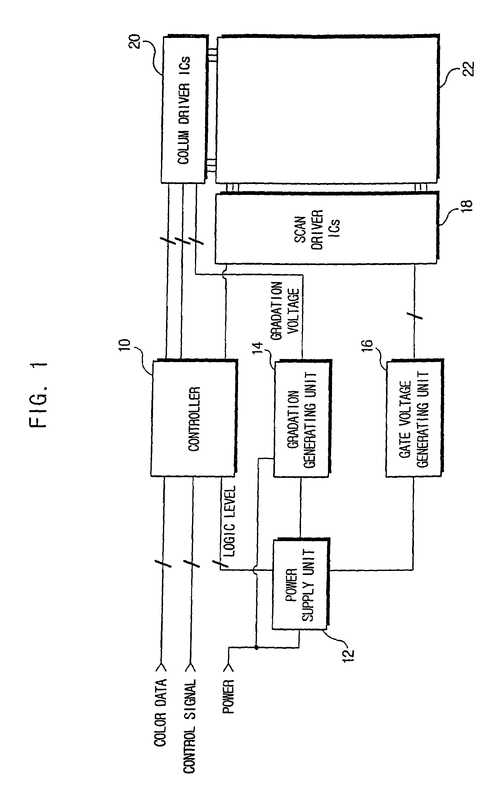
[0025]Referring to FIG. 1, driving circuit of LCD includes a controller 10, column driver ICs 20 and scan driver ICs 18, each of which adopts a shift register.

[0026]The driver circuit of LCD is configured as follows.

[0027]A plurality of bits of color data and control signal are transmitted from a predetermined image supply source such as a main body of computer or an image transmitting device, and input to the controller 10.

[0028]A power supply unit 12 is arranged to supply constant voltages required for the operation of the controller 10, a gradation generating unit 14 and a gate voltage generating unit 16. The gate voltage generating unit 16 is arranged to supply voltages to scan driver ICs 18 so as to generate turn on / off voltages, and the gradation generating unit is arranged to supply gradation voltages to the column driver ICs 20.

[0029]The controller 10 generates control signal...


PUM

PropertyMeasurementUnit
gradation voltageaaaaaaaaaa
gate voltageaaaaaaaaaa
electric power consumptionaaaaaaaaaa

Abstract

A shift register is provided, which adopts a shift operation delay for each memory device, or a data conversion control system through the estimation of conversion of data storage state. A driver circuit of LCD is provided, which adopts such a shift register, to thereby prevent instantaneous increase of electric power consumption while preventing EMI.Accordingly, shift registers operate as being sequentially delayed for each memory device or data conversion is minimized, thus preventing instantaneous excessive consumption of electric power.

Description

CROSS REFERENCE TO RELATED APPLICATIONS[0001]This application is a divisional of U.S. patent application Ser. No. 09 / 886,029, filed Jun. 22, 2001 now abandoned, the disclosure of which is expressly incorporated herein by reference.BACKGROUND OF THE INVENTION[0002]1. Field of the Invention[0003]The present invention in general relates to a shift register and a driver circuit of liquid crystal display adopting the shift register, and more particularly, to a shift register that adopts a shift delay for each memory device, or a data conversion control system through the estimation of conversion of data storage state. The present invention further relates to a driver circuit of LCD adopting such a shift register, which can prevent instantaneous increase of electric power consumption as well as EMI (electromagnetic interference) occurrence.[0004]2. Description of the Related Art[0005]A shift register is a logic circuit having memory devices such as flip flop or latch arranged in line so a...

Claims


Application Information

Patent Timeline
Patent Type & Authority Patents(United States)
IPC IPC(8): G06F3/038G09G5/00G09G3/20G02F1/133G09G3/36G11C19/00
CPCG09G3/3685G09G3/3674G09G2330/021G09G3/36
Inventor PARK, JIN-HOPARK, DONG-WONKWON, OH-JONG
Owner SAMSUNG DISPLAY CO LTD
Why Eureka
Try Eureka