Unlock instant, AI-driven research and patent intelligence for your innovation.
Round wood grinding and polishing equipment
What is Al technical title?
Al technical title is built by PatSnap Al team. It summarizes the technical point description of the patent document.
A log and equipment technology, which is applied in the field of log grinding and polishing equipment, can solve problems such as time-consuming, staff fatigue, etc., and achieve the effects of time saving, convenient use, and uniform speed
Active Publication Date: 2020-08-11
QINGDAO SHUNNENG MACHINERY CO LTD
View PDF9 Cites 38 Cited by
Summary
Abstract
Description
Claims
Application Information
AI Technical Summary
This helps you quickly interpret patents by identifying the three key elements:
Problems solved by technology
Method used
Benefits of technology
Problems solved by technology
[0005] In order to overcome the shortcoming that the staff need to repeatedly push and pull the plane, the staff is tired and consumes a lot of time. Wood Grinding and Polishing Equipment
Method used
Image
Click on the blue label to locate the original text in one second.
Reading with bidirectional positioning of images and text.
Examples
Embodiment 1
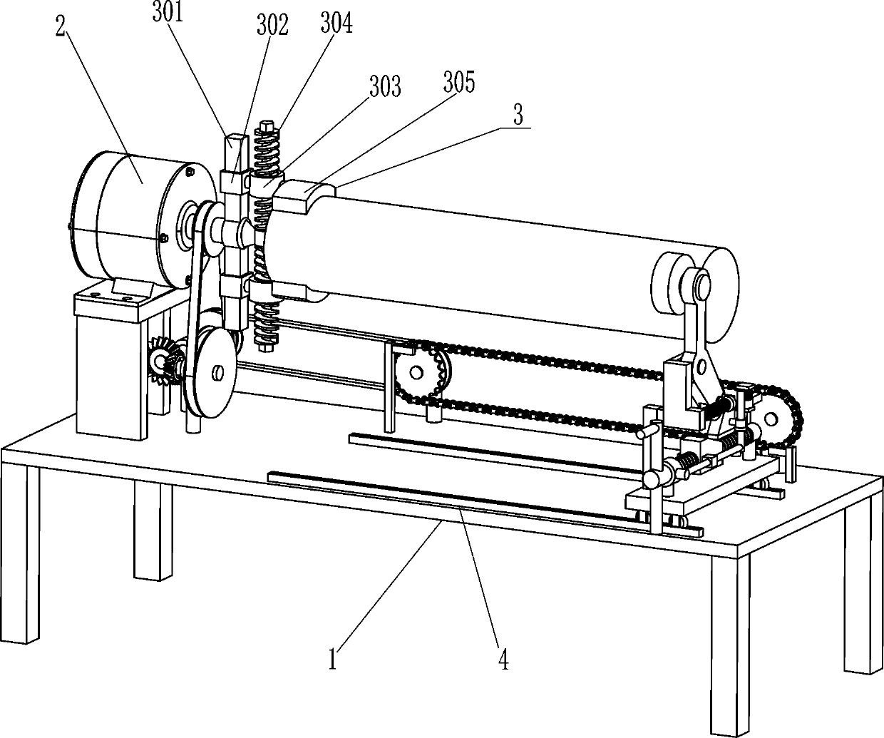
[0024] A kind of log grinding and polishing equipment, such as Figure 1-2 As shown, it includes console 1, geared motor 2, clamping assembly 3, guide rail 4, mounting plate 5, roller 6, and grinding assembly 7. The top left side of console 1 is connected with a mounting bracket, and geared motor 2 is installed by bolts. On the top of the installation frame, guide rails 4 are installed on the front and rear sides of the right side of the top of the console 1 through bolts, and the two guide rails 4 are arranged symmetrically. The sides are equipped with rollers 6, the guide rails 4 are slidingly matched with the rollers 6, and the grinding assembly 7 is installed on the mounting plate 5.
[0025] The clamping assembly 3 includes a rectangular rod 301, a sliding sleeve 302, a first nut 303, a two-way screw mandrel 304 and a clamping block 305. The output shaft of the reduction motor 2 is connected with a rectangular rod 301, and the rectangular rod 301 is slidably provided with...
Embodiment 2
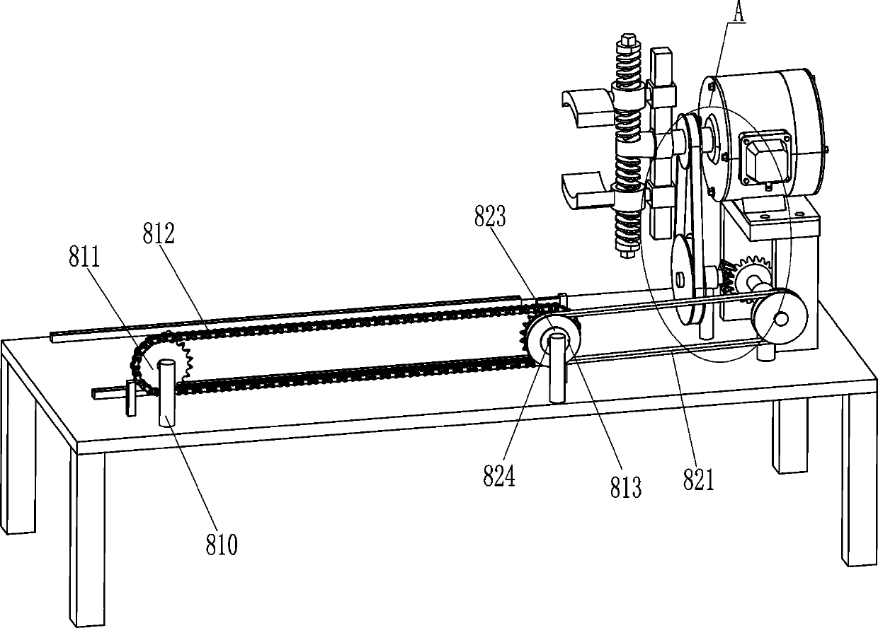
[0031] On the basis of Example 1, such as Figure 3-6 As shown, a moving assembly 8 is also included, and the moving assembly 8 includes a push block 801, a second support sleeve 802, a slide bar 803, a second fixed ring 804, a second spring 805, a first support rod 806, and a limit block 807 , contact block 808, third spring 809, second support rod 810, sprocket wheel 811, chain 812, first transmission wheel 813, second transmission wheel 814, first rotating shaft 815, third transmission wheel 816, first belt 817 , the first bevel gear 818, the second rotating shaft 819, the second bevel gear 820, the second belt 821, the push rod 822, the one-way bearing 823 and the third rotating shaft 824, the left side of the second nut 705 is connected with a push block 801, installed The rear side of the top of the plate 5 is connected with a second support sleeve 802, and the second support sleeve 802 is located on the left side of the first support sleeve 701 on the rear side. The sec...
PUM
Abstract
The invention relates to grinding and polishing equipment, in particular to round wood grinding and polishing equipment. The technical problem of the invention is about provision of the round wood grinding and polishing equipment which can make working personnel easier and save time. The round wood grinding and polishing equipment comprises an operating table, a speed reducing motor, a clamping component, guide rails and the like; the upper side of the operating table is in bolt connection with the speed reducing motor and at least two guide rails; and the clamping component is mounted on thespeed reducing motor and is used for clamping a round wood. According to the round wood grinding and polishing equipment, the round wood can be driven to rotate clockwise through the speed reducing motor; the round wood can be ground by the grinding component, so that the round wood can be rotated automatically and can be ground automatically; therefore, people can be easier and time can be saved;and the leftward moving speed of a grinding wheel can be more uniform through a moving component, so that the grinding and polishing quality of the round wood is not affected.
Description
technical field [0001] The invention relates to a grinding and polishing equipment, in particular to a log grinding and polishing equipment. Background technique [0002] Round wood is cylindrical wood, mainly used to make furniture, such as tables, and can also be used as building materials. After rough machining, the surface of the round wood is still very rough and the smoothness cannot meet the requirements, so the round wood needs to be polished smooth. [0003] At present, the staff mainly hold the plane to polish the log. During the operation, the staff needs to push and pull the plane repeatedly. For a long time, the staff is tired, and the staff needs to turn the log frequently. While polishing, it will consume a lot of time and seriously affect efficiency. [0004] In view of the current problems, we design a device that can make the staff more relaxed and save time. Contents of the invention [0005] In order to overcome the shortcoming that the staff need to...
Claims
Application Information
Patent Timeline
Application Date:The date an application was filed.
Publication Date:The date a patent or application was officially published.
First Publication Date:The earliest publication date of a patent with the same application number.
Issue Date:Publication date of the patent grant document.
PCT Entry Date:The Entry date of PCT National Phase.
Estimated Expiry Date:The statutory expiry date of a patent right according to the Patent Law, and it is the longest term of protection that the patent right can achieve without the termination of the patent right due to other reasons(Term extension factor has been taken into account ).
Invalid Date:Actual expiry date is based on effective date or publication date of legal transaction data of invalid patent.

