Heat insulation doors and windows

A technology for doors and windows and thermal insulation cloth, applied in the field of doors and windows, can solve the problems of falling off of heat-absorbing materials, poor thermal insulation effect of doors and windows, affecting users' living and daily office, etc., to achieve the effect of improving thermal insulation effect and improving stability.

Active Publication Date: 2020-08-11
浙江建瑞幕墙装饰有限公司
View PDF4 Cites 0 Cited by
  • Summary
  • Abstract
  • Description
  • Claims
  • Application Information

AI Technical Summary

Problems solved by technology

[0002] Most of the buildings in the city are high-rise buildings now, and high-rise buildings can save land resources. However, there is a problem in high-rise buildings, that is, high-rise buildings are exposed to sunlight for a long time. In the hot summer, the indoor temperature is high, which seriously affects the living and Daily office, so the current high-rise buildings are using insulated doors and windows
[0003] At present, the heat-insulating doors and windows are all made of double-layer glass, and the surface of each layer of glass is coated with heat-absorbing materials, but the heat-absorbing materials will fall off after a period of use, resulting in poor heat insulation effects of doors and windows; so now Part of the doors and windows are slid between the double-glazed insulation cloth, which is used to reflect the heat radiated by the sun
However, it is inconvenient to move the insulation cloth between the double glazing, making it difficult for the user to adjust the position of the insulation cloth according to the weather conditions, so it needs to be improved

Method used


Image

  • Heat insulation doors and windows
  • Heat insulation doors and windows
  • Heat insulation doors and windows

Examples


Embodiment Construction

[0040] The present invention will be described in further detail below in conjunction with the accompanying drawings.

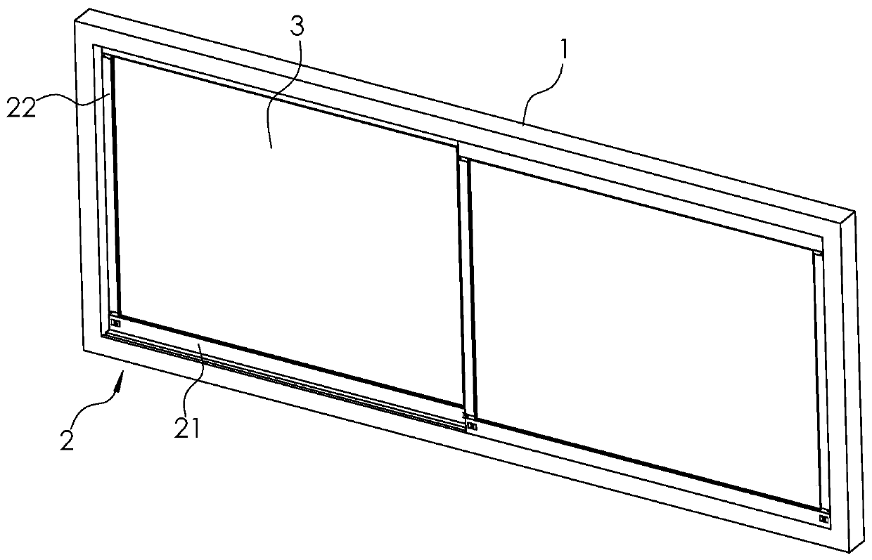
[0041] Such as figure 1 As shown, an insulating door and window includes an outer frame 1, and two sets of windows arranged side by side are slidably fitted in the outer frame 1, and the windows include a window frame 2 and two sets of insulating glass 3 arranged at intervals; the window frame 2 includes two groups of horizontal frames 21 and two groups of vertical frames 22 arranged between the two groups of horizontal frames 21.

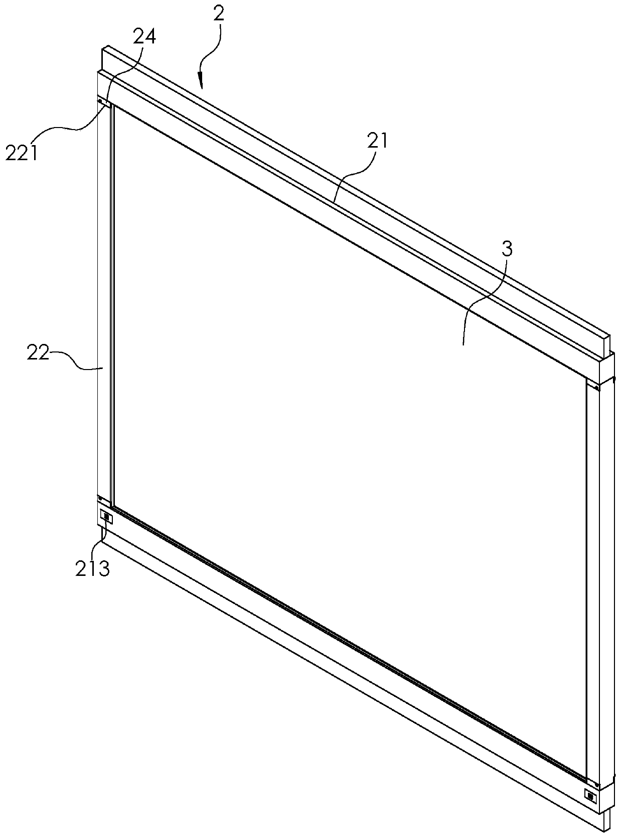
[0042] Such as figure 2As shown, the opposite side of each horizontal frame 21 is fixed with a limiting plate slidably embedded in the outer frame 1 , thereby ensuring the stability of the horizontal frame 21 sliding in the outer frame 1 .

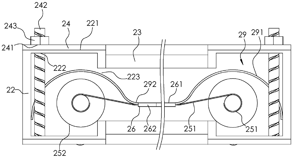
[0043] Such as image 3 and Figure 4 As shown, two sets of clamping pieces for clamping the corresponding vertical frame 22 are fixed on the opposite sides of the two sets of horizontal ...


PUM


Abstract

The invention relates to heat insulation doors and windows. The heat insulation doors and windows comprise an outer frame, two window bodies are arranged in the outer frame in a sliding fit mode, eachwindow body comprises a window frame and two sets of heat insulation glass; two rotating shafts, two magnetic strips, two soft cushions and heat insulation cloth are arranged between the two sets ofheat insulation glass; two traction ropes are wound around each rotating shaft; an attraction part is arranged on each soft cushion; and two through grooves are formed in one side of each window frame. When a user stretches fingers into the through grooves and rotates the rotating shafts, the rotating shafts wind up the traction ropes and drive the soft cushion and the heat insulation cloth to move, and thus the position of the heat insulation cloth can be conveniently adjusted according to needs; when the heat insulation cloth moves to the position between the two rotating shafts, the upper magnetic part and the lower magnetic part attract the corresponding attraction parts, then the two soft cushions are fixed to the window frame, and thus the heat insulation cloth is tensioned in the vertical direction, and the heat insulation effect of doors and windows is improved. According to the heat insulation doors and windows, the position of the heat insulation cloth can be conveniently adjusted according to needs, and the heat insulation effect of doors and windows is improved.

Description

technical field [0001] The invention relates to the technical field of doors and windows, in particular to an insulating door and window. Background technique [0002] Most of the buildings in the city are high-rise buildings now, and high-rise buildings can save land resources. However, there is a problem in high-rise buildings, that is, high-rise buildings are exposed to sunlight for a long time. In the hot summer, the indoor temperature is high, which seriously affects the living and Daily office, so the current high-rise buildings are used insulated doors and windows. [0003] At present, the heat-insulating doors and windows are all made of double-layer glass, and the surface of each layer of glass is coated with heat-absorbing materials, but the heat-absorbing materials will fall off after a period of use, resulting in poor heat insulation effects of doors and windows; so now Some doors and windows have thermal insulation cloth slid between the double glazing to refle...

Claims


Application Information

Patent Timeline
Patent Type & Authority Applications(China)
IPC IPC(8): E06B3/46E06B3/67E06B9/264E06B9/42
CPCE06B3/46E06B3/6715E06B9/264E06B9/42E06B2009/2643
Inventor 章林汉
Owner 浙江建瑞幕墙装饰有限公司
Why Eureka
Try Eureka