Combustion assembly structure of turbojet engine

A technology of turbojet engine and component structure, applied in machine/engine, liquid fuel engine, combustion chamber, etc., can solve the problems of stress relief and recovery performance, complex connection structure, affecting the performance and quality of engine combustion chamber products, etc. The effect of improving printing efficiency

Active Publication Date: 2020-08-11
NAT INST CORP OF ADDITIVE MFG XIAN
View PDF6 Cites 2 Cited by
  • Summary
  • Abstract
  • Description
  • Claims
  • Application Information

AI Technical Summary

Problems solved by technology

The evaporating tube combustion chamber has the advantages of simple structure, easy processing, low cost and good comprehensive combustion performance; for the micro turbojet engine combustion chamber structure that tends to be miniaturized, there are many parts in the micro turbojet engine combustion chamber structure, each part The connection structure between them is complicated. In the combustion chamber of the micro-turbojet engine, the installation connection between the parts leads to the increase of the flow resistance of the combustion assembly, which affects the overall performance of the combustion assembly, and the mechanical structure connection between the parts, the combustion The space needs to meet the installation space. Welding or repair welding in the process of engine combustion chamber manufacturing and parts maintenance in engine combustion chamber manufacturing will lead to loss of material properties. The product performance and quality of the engine combustion chamber. At present, researchers pre-molded the parts in the turbojet engine combustion chamber, but they cannot effectively ensure the combustion efficiency of the turbojet engine combustion chamber and the influence of the flow resistance changes between the parts on the combustion assembly. At present, there is no integrated turbojet engine combustion chamber structure that can ensure the combustion efficiency of the turbojet engine combustion chamber while reducing the size of the turbojet engine combustion chamber.

Method used


Image

  • Combustion assembly structure of turbojet engine
  • Combustion assembly structure of turbojet engine
  • Combustion assembly structure of turbojet engine

Examples


Embodiment Construction

[0035] Below in conjunction with accompanying drawing and specific embodiment the present invention is described in further detail:

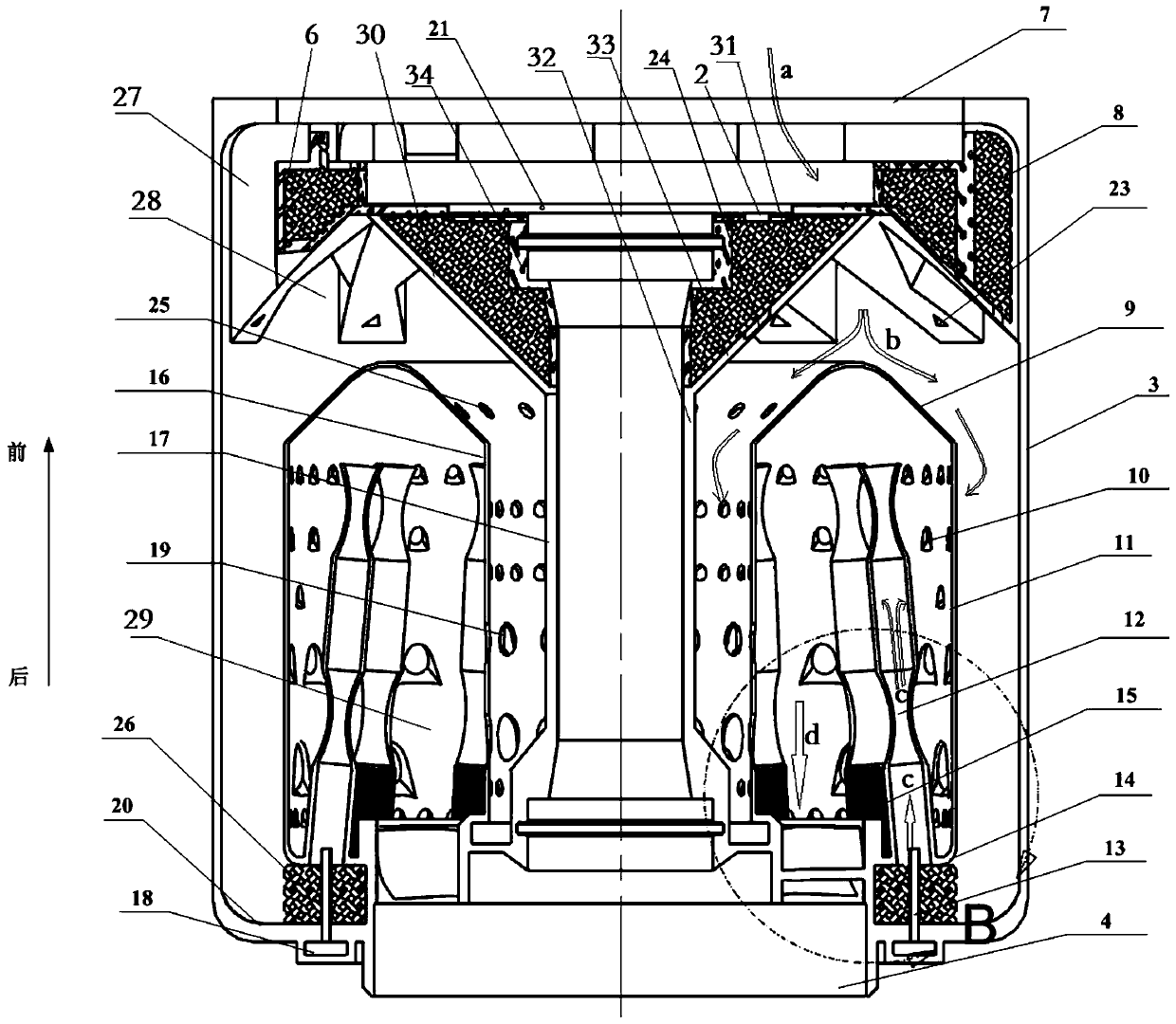
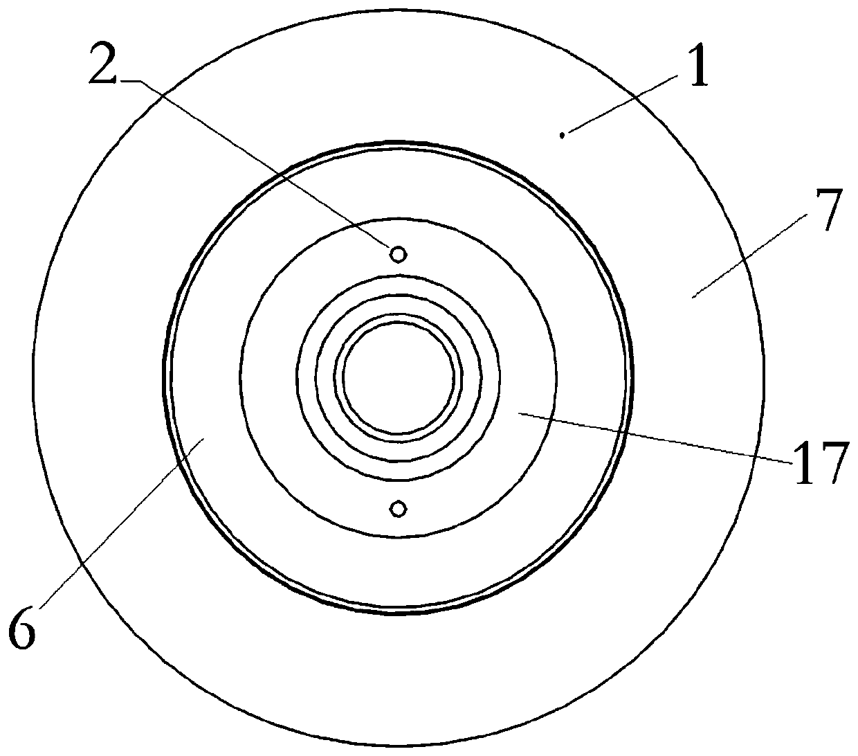
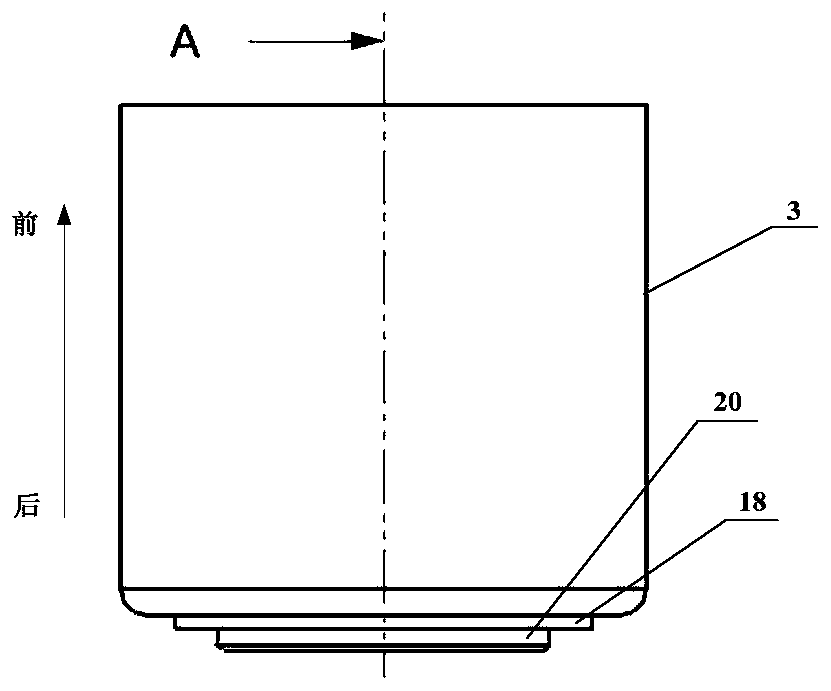
[0036] see Figure 1 to Figure 3 As shown, a turbojet engine combustion assembly structure of the present invention includes a casing 3 with a cavity structure in the middle, and a guide 4 is arranged at one end of the casing 3, and a shaft coaxial with the casing 3 is fixed on the guide 4. Sleeve 17, one end of the shaft sleeve 17 is fixed on the guider 4, and the outer ring of the other end of the shaft sleeve 17 is fixed with a diffuser 6; A diffuser air duct 28 is formed between the two guide vanes 27, a front cover 7 is provided at the end of the diffuser 6, and a circular opening is arranged in the middle of the front cover 7; The section of the 17 axis is V-shaped; the outer ring of the shaft sleeve 17 is provided with a double-layer annular combustion chamber 29 coaxially arranged with the shaft sleeve 17, and the bulkhead wall of the d...


PUM


Abstract

The invention discloses a combustion assembly structure of a turbojet engine. The combustion assembly structure is characterized in that a guider and a front cover are arranged at the two ends of a case with a cavity structure in the middle respectively, a shaft sleeve coaxial with the case is fixed to the guider, a diffuser is fixed to the outer ring of the other end of the shaft sleeve, the sections, along the axis of the shaft sleeve, of the connecting faces between guide vanes and the shaft sleeve are in a V shape, the outer ring of the shaft sleeve is provided with a double-layer annularcombustion tank coaxial with the shaft sleeve, the section, along the axis of the shaft sleeve, of the end face of one end of the double-layer annular combustion tank is V-shaped, the two V-shaped structures enable gas entering from the diffuser to be attached to the wall face of the V-shaped structure of the double-layer annular combustion tank better, meanwhile, the gas entering from the diffuser is prevented from flowing back at a gas inlet, the velocity field is more uniform, the high-speed flow field is optimized, a local high-speed area is avoided, a main combustion area of a combustionchamber can be advanced, and the outlet temperature of the combustion chamber is further reduced; and the axial distance between the diffuser and the double-layer annular combustion tank is reduced, so that the total length of the engine is reduced, the weight of the engine is reduced, and miniaturization of the combustion assembly of the turbojet engine is facilitated.

Description

technical field [0001] The invention belongs to the field of engine combustion structures, and in particular relates to a turbojet engine combustion assembly structure. Background technique [0002] The weight and volume of the combustion chamber itself are an important limitation on the performance of the aircraft. It is an important design direction to reduce the weight and volume while retaining the advantages of the evaporation tube combustion chamber itself. The evaporating tube combustion chamber has the advantages of simple structure, easy processing, low cost and good comprehensive combustion performance; for the micro turbojet engine combustion chamber structure that tends to be miniaturized, there are many parts in the micro turbojet engine combustion chamber structure, each part The connection structure between them is complicated. In the combustion chamber of the micro-turbojet engine, the installation connection between the parts leads to the increase of the flo...

Claims


Application Information

Patent Timeline
Patent Type & Authority Applications(China)
IPC IPC(8): F23R3/14F23R3/52F23R3/28F04D29/54F04D29/58
CPCF04D29/542F04D29/582F23R3/14F23R3/283F23R3/52
Inventor 张琦眭晓蔚代赟杨红伟袁元园杜璧玺程晓东王瑞秦岭卢秉恒
Owner NAT INST CORP OF ADDITIVE MFG XIAN
Why Eureka
Try Eureka