Heat exchanger

A heat exchanger and diffuser technology, applied in heat exchange equipment, indirect heat exchangers, heat exchanger types, etc., can solve problems such as flow distribution damage

Pending Publication Date: 2020-08-11
CARRIER CORP
View PDF6 Cites 0 Cited by
  • Summary
  • Abstract
  • Description
  • Claims
  • Application Information

AI Technical Summary

Problems solved by technology

Consequently, the flow distribution is impaired since it leads to high flow in the end section of the diffuser and low flow in the media section, and also to flow separation

Method used


Image

  • Heat exchanger
  • Heat exchanger
  • Heat exchanger

Examples


Embodiment Construction

[0025] figure 1 A heat exchanger in the form of a submerged evaporator 2 is shown, eg for a refrigeration circuit of a cooler. The submerged evaporator 2 comprises a casing 4 extending along a longitudinal axis X. The casing 4 has a substantially cylindrical shape centered on an axis parallel to the longitudinal direction X.

[0026] The submerged evaporator 2 comprises an inlet pipe 6 and an outlet or suction pipe 8 through which refrigerant flows along the figure 1 Arrows F1 and F2 in enter into and leave from the housing 4 respectively. The submerged evaporator 2 also comprises a tube bundle 10 spanning the shell 4 along the longitudinal axis X. A tube bundle 10 is provided for circulating a flow of water to be cooled in the housing 4 .

[0027] exist figure 1 Above, the tube 10 is shown filling most of the upper half of the shell 4 . However, other distributions of tubes 10 are possible. In particular, the upper quarter of the housing 4 may be free from the tube 10 ...


PUM


Abstract

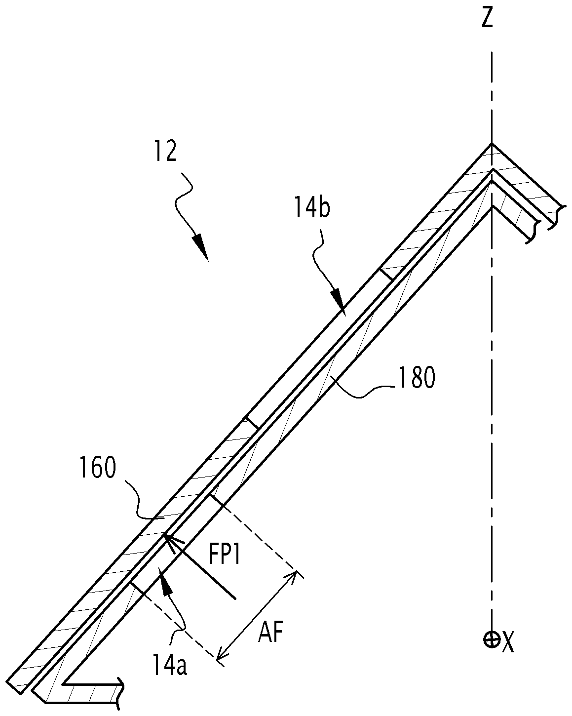
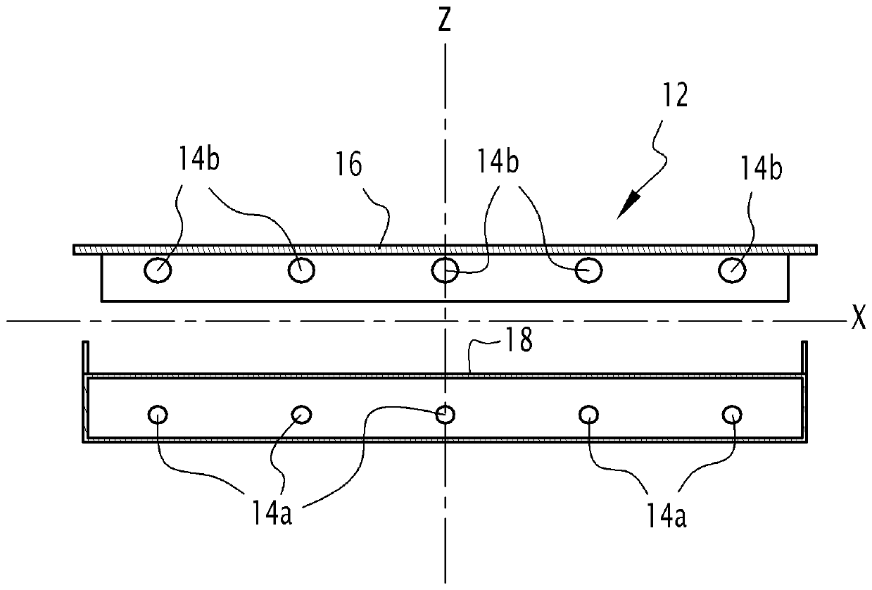
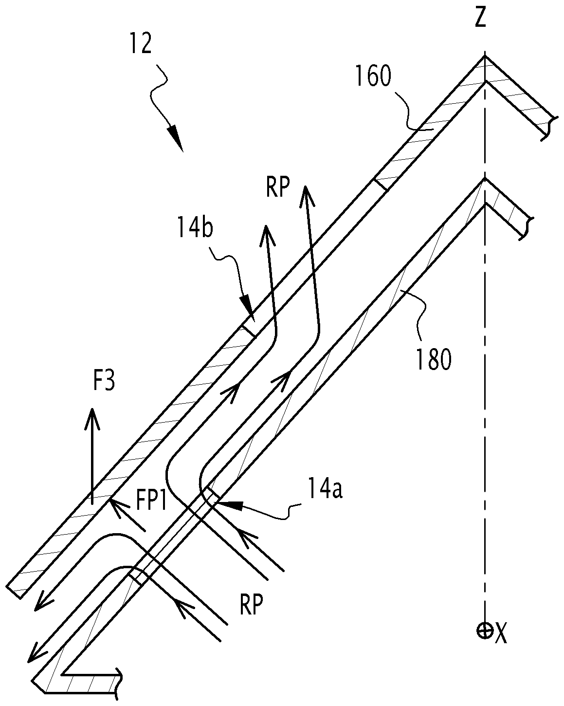
A heat exchanger (2), such as a flooded evaporator, comprises a shell (4) extending along a longitudinal axis (X), an inlet pipe (6) and an outlet pipe (8), through which respectively enters (F1) andexits (F2) a refrigerant flow, and a bundle of pipes (10) crossing the shell (4) along the longitudinal axis (X), and comprising a refrigerant flow diffuser (12) provided inside the shell (4) downstream the inlet pipe (6), the refrigerant flow diffuser (12) extending along the longitudinal axis (X) and comprising openings (14a, 14b) through which the refrigerant flows. The refrigerant flow diffuser (12) comprises a moving element (16) and a stationary element (18), the moving element (16) being movable with respect to the stationary element (18) under action of a pressure force (FP) exerted bythe refrigerant flow so that the refrigerant flow going through the openings (14a, 14b) is adjusted and a differential refrigerant pressure between refrigerant pressure downstream (P2) and upstream (P1) the refrigerant flow diffuser (12) is kept constant.

Description

technical field [0001] The present invention relates to a heat exchanger, such as a flooded evaporator. Background technique [0002] A submerged evaporator for an air handling unit (eg, chiller) includes a shell in which refrigerant gas circulates and in which the liquid phase is mixed. Refrigerant diffusers (diffusers) are used in submerged evaporators to distribute the flow of refrigerant evenly along the length of the shell. [0003] The two-phase refrigerant flow enters a diffuser, which generally has an elongated geometry with openings distributed along the length of the diffuser. The general purpose of a diffuser is to promote an even distribution of refrigerant by choosing an opening geometry that compensates for the changes in the diffuser and evaporator that occur along the length of the diffuser (from the entry section to the axial end section). Changes in pressure differential between shells. Smaller section openings are generally provided in the entry section...

Claims


Application Information

Patent Timeline
Patent Type & Authority Applications(China)
IPC IPC(8): F25B39/02F28F9/00
CPCF25B39/02F28F9/00F28D7/16F28D21/0017F28D2021/0071F28F9/0265F25B39/028F25B2339/0242F25B39/00
Inventor M.格拉邦C.拉哈尔
Owner CARRIER CORP
Why Eureka
Try Eureka