
A multifunctional integrated condensing evaporator for a cascade refrigeration system

A technology of condensing evaporator and cascade refrigeration, applied in the direction of evaporator/condenser, refrigerator, refrigeration components, etc., can solve the problem of shortening the service life of heat exchanger, large amount of working medium, and excessive temperature difference of heat exchanger. and other problems, to achieve the effect of eliminating the influence of temperature difference stress, high utilization rate of heat exchange area, and improving system reliability

Active Publication Date: 2021-11-02
山东智珩环境设备有限公司
View PDF6 Cites 0 Cited by
  • Summary
  • Abstract
  • Description
  • Claims
  • Application Information

AI Technical Summary

Problems solved by technology

[0003] The above scheme has the following disadvantages: 1. The condensing evaporator components are bulky and the charging volume of the working fluid is large, which is not conducive to the integrated design of the cascade system; 2. The compressor exhaust is directly condensed, and the temperature difference between the two sides of the heat exchanger is too large ( The exhaust superheat degree on the low-temperature side is very high, the exhaust temperature is about 80°C, the medium temperature on the high-temperature side is -30°C, and the temperature difference between the two sides reaches more than 100°C at the inlet of the heat exchanger). Damage to the heat exchanger shortens the service life of the heat exchanger and affects the reliability of the entire cascade refrigeration system; 3. Liquid level control and oil return control are required for flooded and gravity liquid-fed condensing evaporators. The control of the expansion condensing evaporator is simpler and more reliable; 4. The condensate has no or little subcooling, which is not convenient for long-distance transportation

Method used


Image

  • A multifunctional integrated condensing evaporator for a cascade refrigeration system
  • A multifunctional integrated condensing evaporator for a cascade refrigeration system
  • A multifunctional integrated condensing evaporator for a cascade refrigeration system

Examples


Embodiment Construction

[0026] The technical scheme of the present invention is described in detail below in conjunction with accompanying drawing:

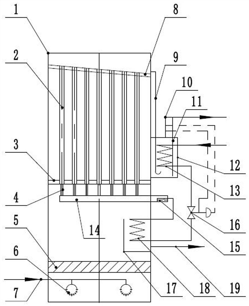
[0027] Such as figure 1 , a multifunctional integrated condensing evaporator for a cascade refrigeration system, comprising a shell 1, an upper tube plate 8 and a rectifying layer 5 are arranged in the shell 1 from top to bottom, and the inner cavity of the shell 1 is divided into Return air chamber, upper heat exchange chamber and lower heat exchange chamber from top to bottom. Wherein, the upper tube sheet 8 is set at an inclination of 5°.

[0028] The condensing evaporator also includes an inlet pipe 7 communicating with the lower heat exchange chamber and a liquid outlet pipe 19 communicating with the upper heat exchange chamber. Specifically, the air intake pipe 7 communicates with the rotary diffuser 6 installed in the lower heat exchange chamber. The upper heat exchange chamber is also provided with a deflector 17 located below the heat exchan...


PUM


Abstract

The invention discloses a multifunctional integrated condensing evaporator of a cascading refrigeration system, which comprises a shell, and an upper tube plate and a rectifying layer are arranged in the shell from top to bottom, and the inner cavity of the shell is divided into top to bottom parts. The air return chamber, the upper heat exchange chamber and the lower heat exchange chamber; the condensing evaporator also includes an inlet pipe communicated with the lower heat exchange chamber and a liquid outlet pipe communicated with the upper heat exchange chamber; the condensing evaporator also includes Including the evaporation side pipeline, the evaporation side pipeline includes a heat exchange tube assembly arranged in the upper heat exchange chamber, the upper end of the heat exchange tube of the heat exchange tube assembly communicates with the return air chamber; the evaporation side pipe The circuit also includes a first heat exchange device for heating the liquid separated in the return air chamber and a second heat exchange device for subcooling the liquid condensed in the lower heat exchange chamber. The invention has the advantages of good heat exchange performance, low charging amount, small volume and the like.

Description

technical field [0001] The invention relates to the technical field of refrigeration, in particular to an integrated condensation evaporator of a cascade refrigeration system. Background technique [0002] The cascade refrigeration system is widely used, and the condensing evaporator is the key heat exchange component. The condensing evaporator of the cascade refrigeration system mostly adopts the flooded or gravity liquid supply type, which has the advantage of obtaining better heat transfer performance and improving the overall operating efficiency of the system. [0003] The above scheme has the following disadvantages: 1. The condensing evaporator components are bulky and the charging volume of the working medium is large, which is not conducive to the integrated design of the cascade system; 2. The exhaust gas of the compressor is directly condensed, and the temperature difference between the two sides of the heat exchanger is too large ( The exhaust superheat degree o...

Claims


Application Information

Patent Timeline
Patent Type & Authority Patents(China)
IPC IPC(8): F25B39/02F25B39/04F25B7/00
CPCF25B7/00F25B39/02F25B39/04
Inventor 韩献军宋立斌
Owner 山东智珩环境设备有限公司
Learn More