Small torque rapid detection device and detection method
A detection device and torque technology, which is applied in the field of small torque rapid detection devices, can solve the problems of low cost and efficiency of torque detection, and achieve the effects of simple structure, low use and maintenance costs, and improved accuracy
- Summary
- Abstract
- Description
- Claims
- Application Information
AI Technical Summary
Problems solved by technology
Method used
Image
Examples
Embodiment 1
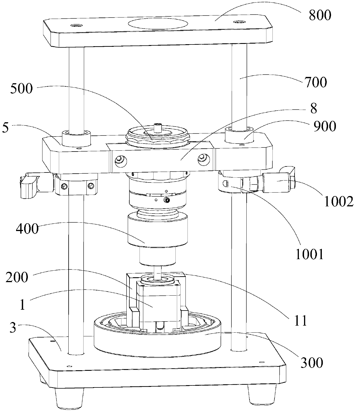
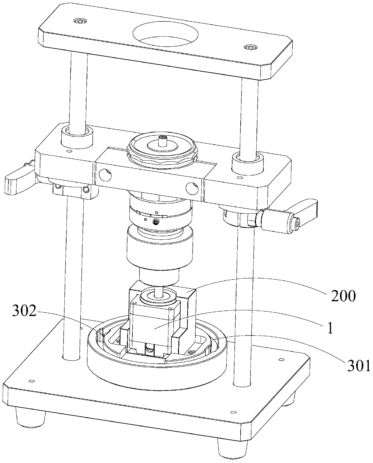
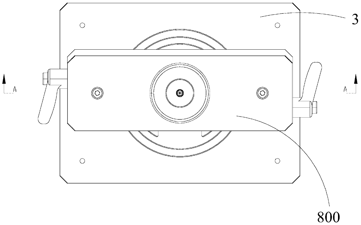
[0049] Such as Figure 1 to Figure 7 As shown, this embodiment provides a small-sized torque fast detection device, which is suitable for detecting the torque of the output shaft 11 of the shaft component, that is, the measured object 1 referred to below is a shaft component. Specific object 1 takes a stepping motor as an example.
[0050] Specifically, the small-sized torque rapid detection device of this embodiment includes: a positioning and rotating mechanism suitable for placing the measured object 1 and positioning the measured object 1 and driving the measured object 1 to rotate together; The torque detection mechanism is used to detect the torque of the object 1 rotated by the positioning rotation mechanism.
[0051]In more detail, first, the positioning and rotating mechanism includes a positioning piece 200 suitable for supporting the object under test 1, and a rotating piece 300 suitable for driving the positioning piece 200 to rotate. After the object under test 1...
Embodiment 2
[0071] On the basis of the small torque rapid detection device in embodiment 1, this embodiment provides a small torque rapid detection method, including:
[0072] Step S1: Select the suitable positioning part 200 and connecting part 400 according to the specifications of the object under test 1, match the selected positioning part 200 with the rotating part 300, and match the selected connecting part 400 with the torque tester 500 catch.
[0073] Step S2: After the object under test 1 is put into the positioning member 200, move the fixing base 5 along the guide column 700 toward the base 3, so that the output shaft 11 of the object under test 1 is gradually pressed into the connecting member 400. In the one-way bearing 600 , the connection between the connecting piece 400 and the output shaft 11 of the object under test 1 is completed.
[0074] Step S3: After the object under test 1, the positioning part 200 and the connecting part 400 are matched in place, the rotation of ...
PUM
 Abstract
Description
Claims
Application Information
 - R&D
- Intellectual Property
- Life Sciences
- Materials
- Tech Scout
- Unparalleled Data Quality
- Higher Quality Content
- 60% Fewer Hallucinations
Browse by: Latest US Patents, China's latest patents, Technical Efficacy Thesaurus, Application Domain, Technology Topic, Popular Technical Reports.
© 2025 PatSnap. All rights reserved.Legal|Privacy policy|Modern Slavery Act Transparency Statement|Sitemap|About US| Contact US: help@patsnap.com


