
Electric connector and connector combination

A connector combination and electrical connector technology, applied in the direction of connection, fixed connection, and parts of the connection device, to achieve the effect of enhancing suppression, increasing coupling, and reducing mutual interference

Active Publication Date: 2020-08-11
DEYI PRECISION ELECTRONIC IND CO LTD PANYU
View PDF8 Cites 10 Cited by
  • Summary
  • Abstract
  • Description
  • Claims
  • Application Information

AI Technical Summary

Problems solved by technology

With the upgrading of the PCI-E protocol, the signal transmission rate required by it is getting higher and higher, and the electrical coupling formed by the conventional conductive terminals arranged at equal intervals does not help the electrical connector to increase its signal transmission rate. Meet the requirements of the new generation PCI-E protocol

Method used


Image

  • Electric connector and connector combination
  • Electric connector and connector combination
  • Electric connector and connector combination

Examples


Embodiment Construction

[0046] In order to facilitate a better understanding of the purpose, structure, features, and effects of the present invention, the present invention will now be further described in conjunction with the accompanying drawings and specific embodiments.

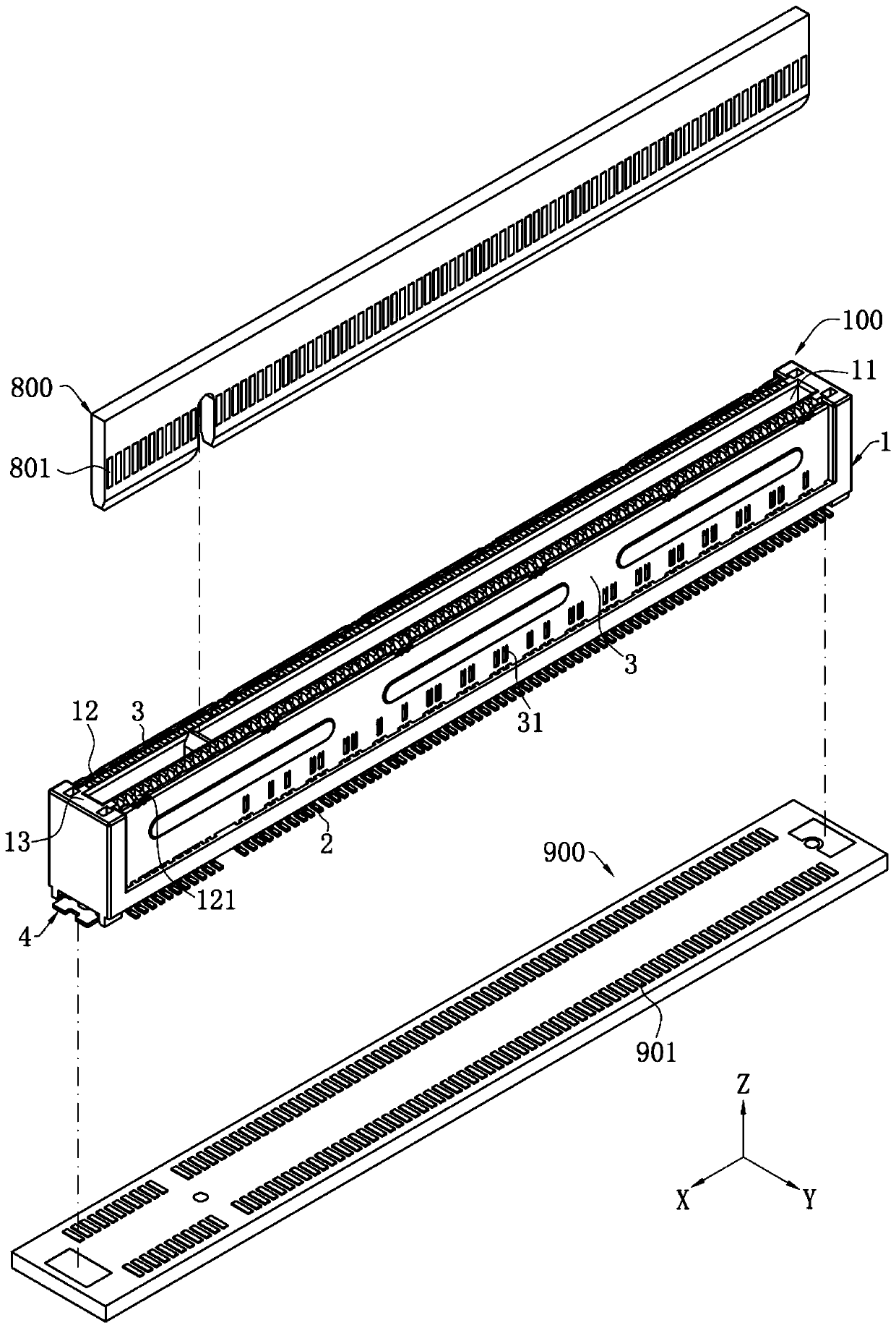
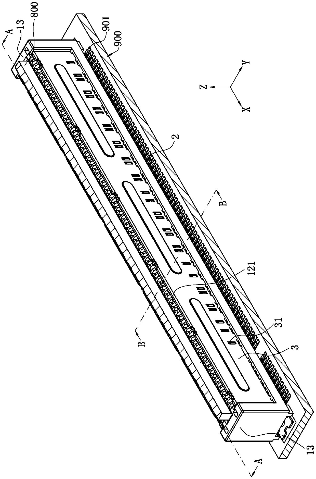
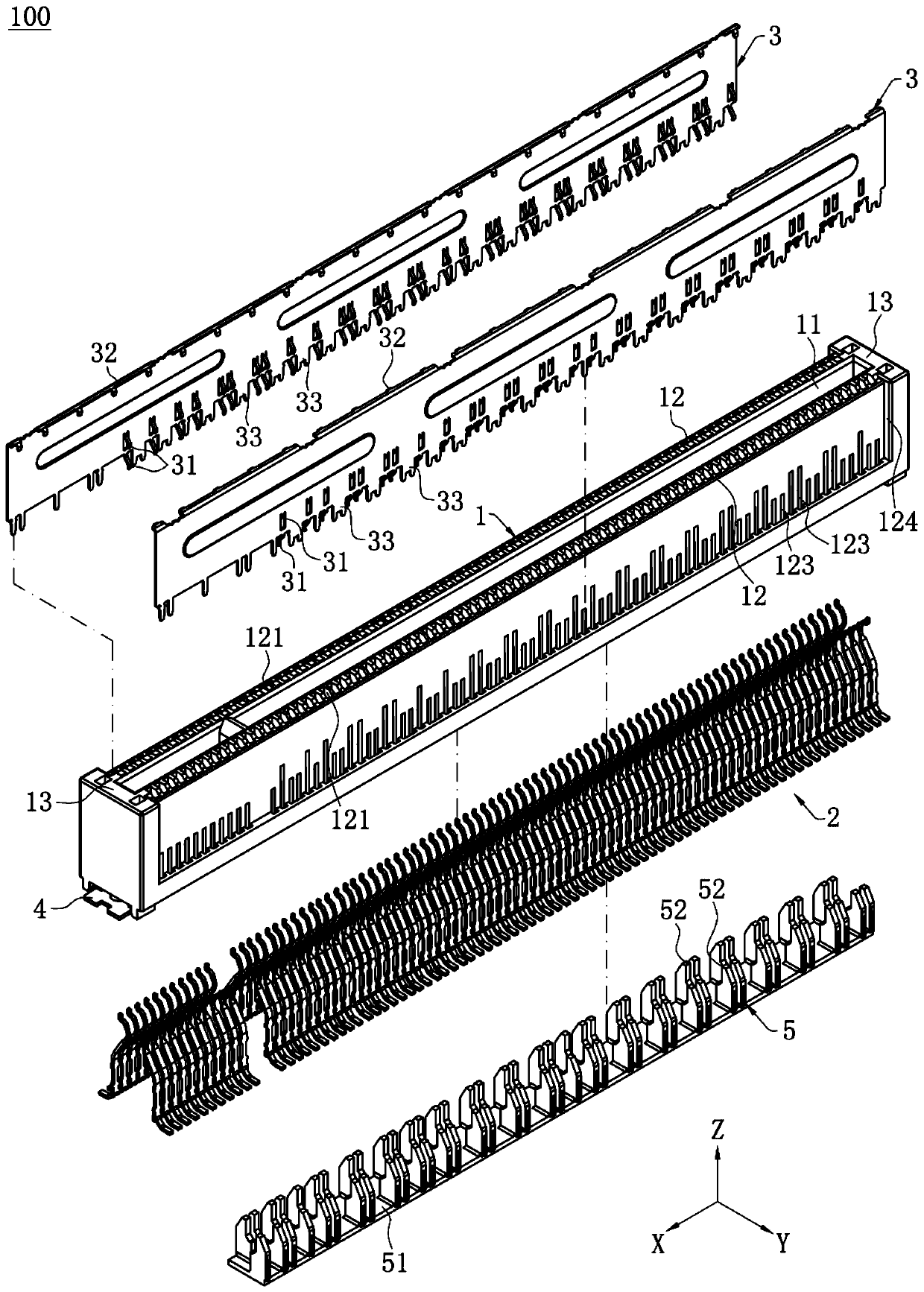
[0047] Such as figure 1 and figure 2 As shown, it is the connector assembly of the present invention, the connector assembly includes an electrical connector 100, a pair of docking elements 800 and a circuit board 900, the docking element 800 is connected to the circuit through the electrical connector 100 The board 900 forms an electrical connection. In this embodiment, the electrical connector 100 is a vertical card edge connector installed downward on the circuit board 900. The docking element 800 is a PCI-E An electronic card of the transmission protocol is plugged downwardly into the electrical connector 100 . In the accompanying drawings of the present invention, the X-axis direction represents the longitudinal directi...


PUM


Abstract

The invention discloses an electric connector and a connector combination. The electric connector comprises a base; a row of conductive terminals, comprising a plurality of signal terminals and a plurality of grounding terminals, each conductive terminal being provided with a contact part in contact with the butt joint element, the row of conductive terminals comprising a terminal group, the terminal group comprising two grounding terminals and a differential signal terminal pair located between the two grounding terminals, and the differential signal terminal pair being composed of two adjacent signal terminals. In the same terminal group, the distance between two adjacent signal terminals is defined as a first distance, the distance between each signal terminal and the grounding terminaladjacent to the signal terminal is defined as a second distance, and the first distance is smaller than the second distance. Another grounding terminal adjacent to the terminal group is arranged outside the terminal group, the distance between the other grounding terminal and the adjacent grounding terminal in the terminal group is defined as a third distance, and the third distance is larger than the second distance. The butt joint element is provided with conductive gaskets which are arranged at equal intervals, and the electric connector and the butt joint element form a connector combination.

Description

【Technical field】 [0001] The invention relates to an electric connector and a connector combination, in particular to an electric connector and a connector combination whose conductive terminals are arranged at unequal intervals. 【Background technique】 [0002] The conventional connector combination includes electric connectors and docking elements that are docked with each other, and a plurality of conductive terminals arranged at equal intervals in the electrical connector and a plurality of butt terminals arranged at equal intervals in the docking element are connected one by one. , realize the signal transmission between the electrical connector and the docking element, for example, the electrical connector is a card edge connector conforming to the PCI-E transmission protocol, the docking element is an electronic card, and according to the PCI-E However, for electronic cards using this transmission protocol, the conductive pads are arranged at equal intervals, so it is ...

Claims


Application Information

Patent Timeline
Patent Type & Authority Applications(China)
IPC IPC(8): H01R13/6581H01R13/6591H01R13/24H01R12/72
CPCH01R13/6581H01R13/6591H01R13/24H01R12/72H01R12/737H01R12/721H01R13/6477H01R13/6471H01R12/58
Inventor 吴瑶张文昌张标殷佳旭梁崇成
Owner DEYI PRECISION ELECTRONIC IND CO LTD PANYU
Learn More