Leg raising device for medical care

A technology for heightening and legs, applied in nursing facilities, medical science, hospital equipment, etc., can solve the problems of not being able to adapt to different types of feet, and achieve the effects of preventing displacement, stable use, and good treatment

Inactive Publication Date: 2020-08-14
尹明
View PDF15 Cites 1 Cited by
  • Summary
  • Abstract
  • Description
  • Claims
  • Application Information

AI Technical Summary

Problems solved by technology

[0005] In order to overcome the shortcomings of current foot support devices that cannot adapt to different types of feet, t

Method used


Image

  • Leg raising device for medical care
  • Leg raising device for medical care
  • Leg raising device for medical care

Examples


Embodiment 1

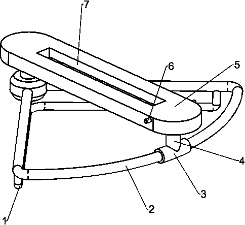
[0023] A leg raising device for medical care, such as Figure 1-4 As shown, it includes a support frame 1, a front and rear angle adjustment assembly, a foot placement assembly and an up and down angle adjustment assembly. There is a foot placement assembly for supporting the feet, and the front side of the front and rear angle adjustment assembly is provided with an up and down angle adjustment assembly for adjusting the up and down angles by sliding.

[0024] like figure 1 and 2 As shown, the front and rear angle adjustment components include an arc guide rod 2, an arc sliding sleeve 3, a circular block 4, a mounting plate 5 and a hinge rod 6, the right side of the support frame 1 is welded with an arc guide rod 2, and the arc guide rod 2 is welded on the right side of the support frame 1. The rod 2 is slidingly provided with an arc-shaped sliding sleeve 3, and the top of the arc-shaped sliding sleeve 3 is welded with a circular block 4. The top of the circular block 4 is ...

Embodiment 2

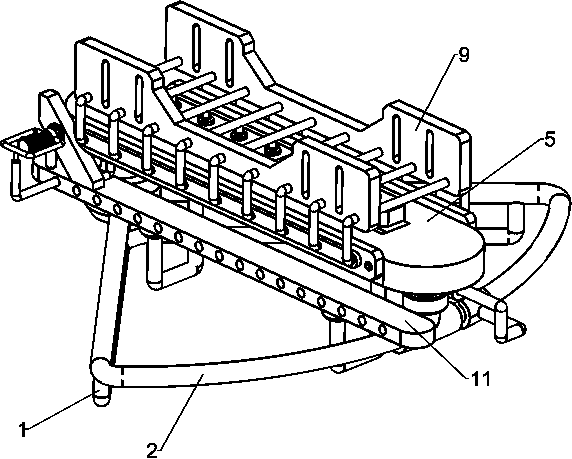
[0032] On the basis of Example 1, such as figure 1 , 5 Shown in and 6, also include slide rail 16, slide block 17 and support bar 18, place rack 9 inner bottoms are fixedly connected with slide rail 16 by bolt, slide type is provided with slide block 17 in slide rail 16, slide groove 7 The left rotating type is provided with a support rod 18, and the right end of the support rod 18 is rotationally connected with the slide block 17.

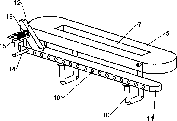
[0033] like figure 1 and 7 Shown, also comprise guide sleeve 19, pull bar 20, second spring 21 and arc-shaped rubber cover 22, circular block 4 middle part rear sides are welded with guide sleeve 19, slide type is provided with pull bar 20 in guide sleeve 19, pull bar 20 A second spring 21 is connected between the left part and the left side of the guide sleeve 19, and an arc-shaped rubber sleeve 22 is connected to the front end of the pull rod 20, and the arc-shaped rubber sleeve 22 is pressed on the arc-shaped guide rod 2.

[0034] The worki...


PUM


Abstract

The invention relates to a raising device, and in particular relates to a leg raising device for medical care. The technical problem to be solved is to provide a leg raising device for medical care, which can support feet in different postures. The leg raising device for medical care comprises a supporting frame, a front-back angle adjusting assembly, a foot placing assembly, and an up-down angleadjusting assembly, wherein the front-back angle adjusting assembly is installed on the supporting frame, and used for changing a front-back angle of a foot in a sliding mode; the foot placing assembly is installed on the front-back angle adjusting assembly and used for supporting the foot; and the up-down angle adjusting assembly is installed on the front-back angle adjusting assembly and carriesout up-down angle adjustment in a sliding mode. By means of the front-back angle adjusting assembly, the device can adapt to the feet of different types, meanwhile, a patient can be supported withoutchanging the position of the patient; and by means of the up-down angle adjusting assembly, a foot supporting angle of the patient can be changed, so that the patient can be better treated.

Description

technical field [0001] The invention relates to a raising device, in particular to a leg raising device for medical care. Background technique [0002] With the development and progress of society and the improvement of people's living standards, the demand for nurses is increasing, and the requirements are getting higher and higher. More and more migrant workers have entered the nursing industry. In hospitals, communities or families, many patients have accepted the services provided by nursing workers. When a person's lower limbs are injured, the use of physical height can significantly promote the blood return of the limbs and eliminate swelling. [0003] The patent authorization announcement number is CN21085925U, which discloses a lower limb raising pad for medical care, including a raising pad body; one side of the raising pad body along the length direction is a knee pad, a leg pad and a foot pad, and the three Integral structure; the knee pad is a slope body with a...

Claims


Application Information

Patent Timeline
IPC IPC(8): A61G12/00A61B90/14A61G7/075
CPCA61G7/0755A61G12/00A61B90/14
Inventor 石群
Owner 尹明
Why Eureka
Try Eureka