Method for replacing filter of dust collecting device, dust collecting device and filter
A dust collection device and replacement method technology, which is applied to chemical instruments and methods, separation methods, filtration and separation, etc., can solve the problems of different, limited range of filter selection, etc., and achieve the effect of expanding the application range
- Summary
- Abstract
- Description
- Claims
- Application Information
AI Technical Summary
Problems solved by technology
Method used
Image

Examples
no. 1 Embodiment approach 〕
[0023] One embodiment of the present invention will be described in detail below.
[0024] (the overall structure of the filter)
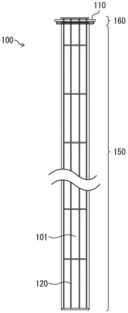
[0025] figure 1 It is a schematic diagram showing the filter 100 according to the first embodiment. The filter 100 has a vertically long shape as a whole. Most of the filter 100 constitutes a cylindrical filter unit 150 . The total length of the filter unit 150 is about 1 to 10 m. The diameter of the filter unit 150 is about 10 to 17 cm.
[0026] The filter 100 includes an attachment portion 160 on the top of the filter portion 150 . The filter part 150 is comprised from the filter cloth 101 formed in cylindrical shape. The bottom of the filter cloth 101 is closed, and the filter cloth 101 is a vertically long bag shape with an upper part opened. In addition, a frame (namely, a holder 120 ) for maintaining the shape of the filter cloth 101 is provided on the filter unit 150 .
[0027] The filter cloth 101 is made of heat-resistant material....
no. 2 Embodiment approach 〕
[0055] Another embodiment of the present invention will be described below. In addition, for convenience of description, components having the same functions as those described in the above-mentioned embodiments are denoted by the same reference numerals, and redundant descriptions are omitted.
[0056] The overall structure of the filter 200 according to the second embodiment is the same as that of the filter 100 according to the first embodiment, but the structure of the attachment part is different. Below, use Figure 4 The attachment part of the filter 200 is demonstrated in detail. exist Figure 4 In , the structure near the attachment part of the filter 200 and the simple plate 3 are shown.
[0057] The belt portion 202 is connected to the top of the cylindrical filter cloth 201 . Here, the band portion 202 is a band-shaped portion formed on the top of the cylindrical portion. The belt portion 202 may be formed by extending the filter cloth 201 directly, or may be f...
no. 3 Embodiment approach 〕
[0063] The overall structure of the filter 300 according to the third embodiment is the same as that of the filter 200 according to the second embodiment, but the structure of the attachment part is different. Below, use Figure 5 The attachment part of the filter 300 is demonstrated in detail. exist Figure 5 In , the structure near the attachment part of the filter 300 and the simple plate 3 are shown.
[0064] The belt portion 302 is connected to the top of the cylindrical filter cloth 301 . Here, the band portion 302 is a band-shaped portion formed on the top of the cylindrical portion. The belt portion 302 may be formed by extending the filter cloth 301 directly, or may be formed by connecting another cloth material. A detent 303 made of metal is fixed to the belt portion 302 . The detent 303 is an annular member that fits into the circular opening 3 a of the simple plate 3 . The bayonet pin 303 has elasticity, and when it fits in the opening part 3a, the filter clo...
PUM
 Abstract
Description
Claims
Application Information
 - R&D
- Intellectual Property
- Life Sciences
- Materials
- Tech Scout
- Unparalleled Data Quality
- Higher Quality Content
- 60% Fewer Hallucinations
Browse by: Latest US Patents, China's latest patents, Technical Efficacy Thesaurus, Application Domain, Technology Topic, Popular Technical Reports.
© 2025 PatSnap. All rights reserved.Legal|Privacy policy|Modern Slavery Act Transparency Statement|Sitemap|About US| Contact US: help@patsnap.com