Die cutting mechanism and die cutting machine
A die-cutting and die-cutting knife technology, applied in metal processing and other directions, can solve the problems of low tearing efficiency, multi-manpower, manual tearing, etc., to reduce the use of manpower and improve efficiency.
- Summary
- Abstract
- Description
- Claims
- Application Information
AI Technical Summary
Problems solved by technology
Method used
Image
Examples
Embodiment 1
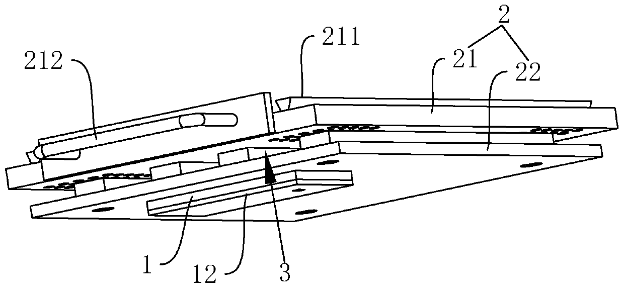
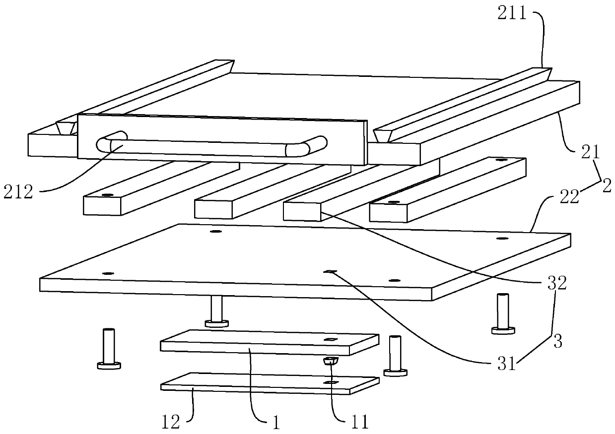
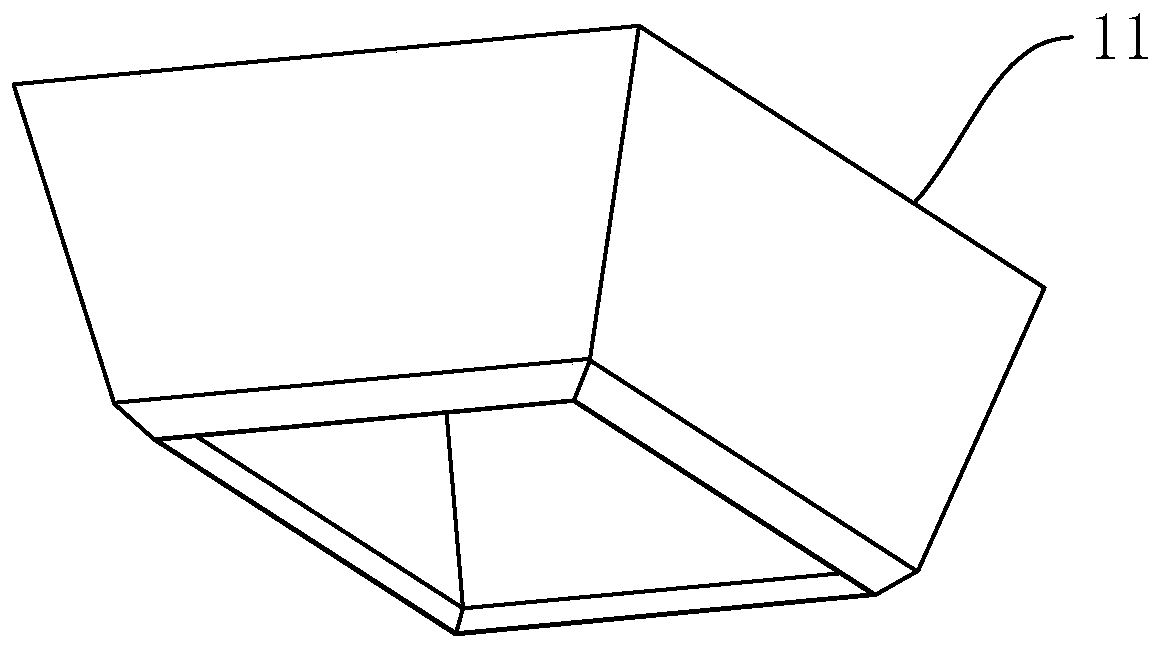
[0035] Embodiment one, with reference to figure 1 and figure 2 , is a die-cutting mechanism disclosed in the present invention, which can carry the remaining material generated by cutting from the perforation while cutting and forming a perforation, without the need for subsequent manual tearing of the remaining material; The die-cutting mechanism includes a mounting plate 1, which is made of stainless steel. In this embodiment, the mounting plate 1 is in the shape of a cuboid. In other embodiments, the mounting plate 1 can also be in the shape of a disc; A die cutter 11 is provided, and the die cutter 11 is made of stainless steel. In this embodiment, the die cutter 11 is in the shape of a square ring, and in other embodiments it can also be in the shape of a ring or a waist ring. , the shape of the die-cutter 11 should be selected according to the shape actually needed for the perforation on the label; the cutting edge of the die-cutter 11 is arranged at the port at one en...
Embodiment 2
[0043] Embodiment two, refer to Figure 4 and Figure 5 , a die-cutting machine, comprising: upper die base 4, lower die base 5 and drive rod 6, upper die base 4 and lower die base 5 are in the shape of a cuboid and are made of carbon steel, upper die base 4 and lower die base The seat 5 is set up and down oppositely; the lower mold seat 5 is fixed on a workbench by bolts; the drive rod 6 is cylindrical, and in this embodiment, the drive rod 6 is provided with four vertically parallel to each other, and the four drive rods 6 Respectively vertically fixed on the four corners of the upper mold base 4 near the surface of the lower mold base 5, and the end of the drive rod 6 away from the upper mold base 4 passes through the lower mold base 5 and is inserted below the workbench. The lower mold base 5 is slidingly connected, and the driving rod 6 is fixedly connected with the upper mold base 4 by bolts; the way of driving the driving rod 6 to move up and down can be driven up and ...
PUM
 Abstract
Description
Claims
Application Information
 - R&D
- Intellectual Property
- Life Sciences
- Materials
- Tech Scout
- Unparalleled Data Quality
- Higher Quality Content
- 60% Fewer Hallucinations
Browse by: Latest US Patents, China's latest patents, Technical Efficacy Thesaurus, Application Domain, Technology Topic, Popular Technical Reports.
© 2025 PatSnap. All rights reserved.Legal|Privacy policy|Modern Slavery Act Transparency Statement|Sitemap|About US| Contact US: help@patsnap.com


