Foam board cutting equipment

A cutting equipment, foam board technology, applied in the direction of removing smoke and dust, recycling technology, metal processing, etc., can solve the problem of not being able to remove toxic gas, health effects, foam board burns, etc.

Active Publication Date: 2020-08-14
南通科橙机器人有限公司
View PDF9 Cites 1 Cited by
  • Summary
  • Abstract
  • Description
  • Claims
  • Application Information

AI Technical Summary

Problems solved by technology

[0004] In order to overcome the disadvantages that the toxic gas cannot be taken away during the cutting process, which may easily cause the toxic gas to affect people's health, and the foam board after cutting is easy to contact with the hand and be burned. Therefore, the technical problem of the present invention is: to provide a A foam board cutting equipment that can remove toxic gas without affecting people's health, and can also prevent hands from being scalded by the cut foam board

Method used


Image

  • Foam board cutting equipment
  • Foam board cutting equipment
  • Foam board cutting equipment

Examples


Embodiment 1

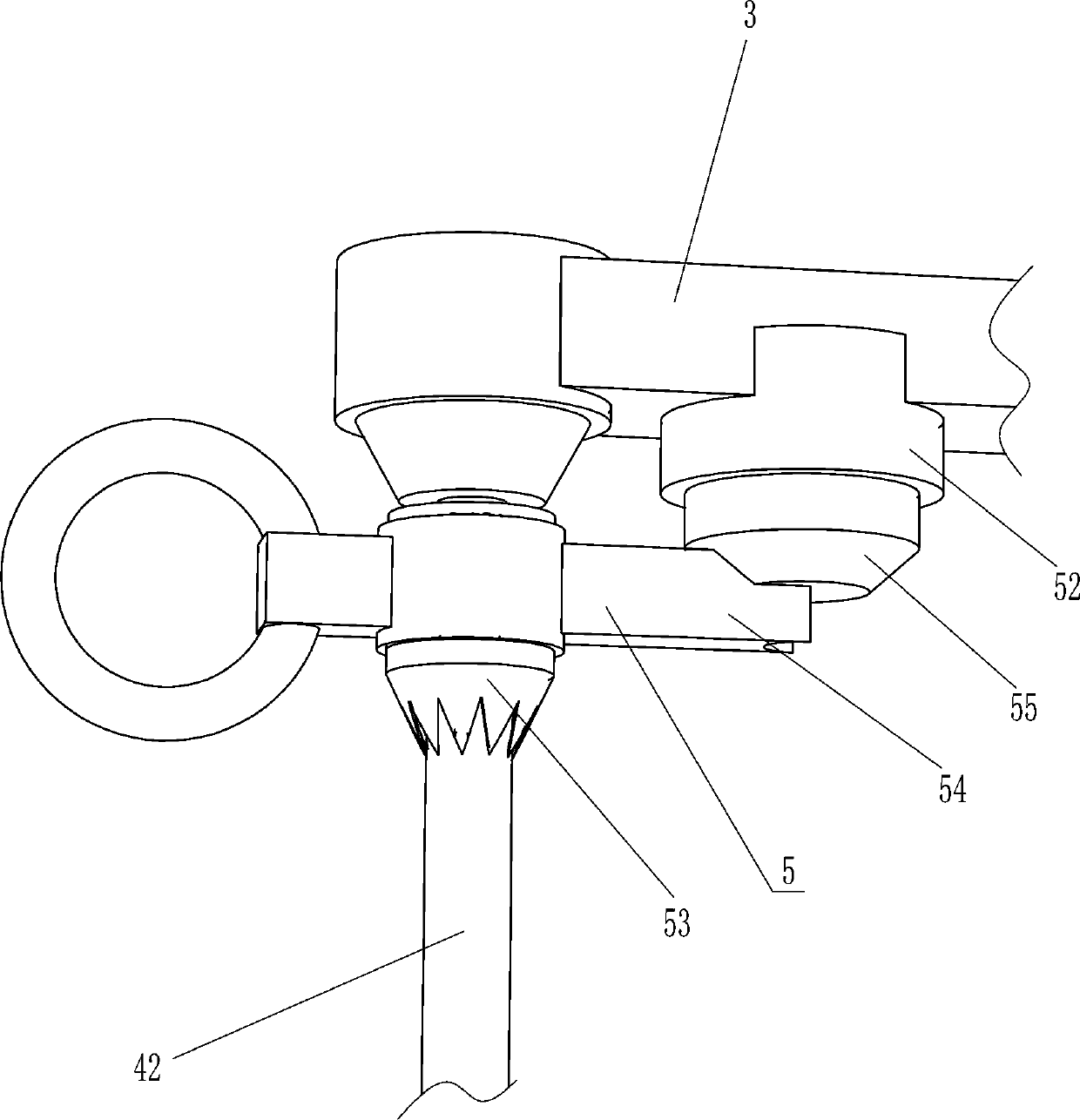
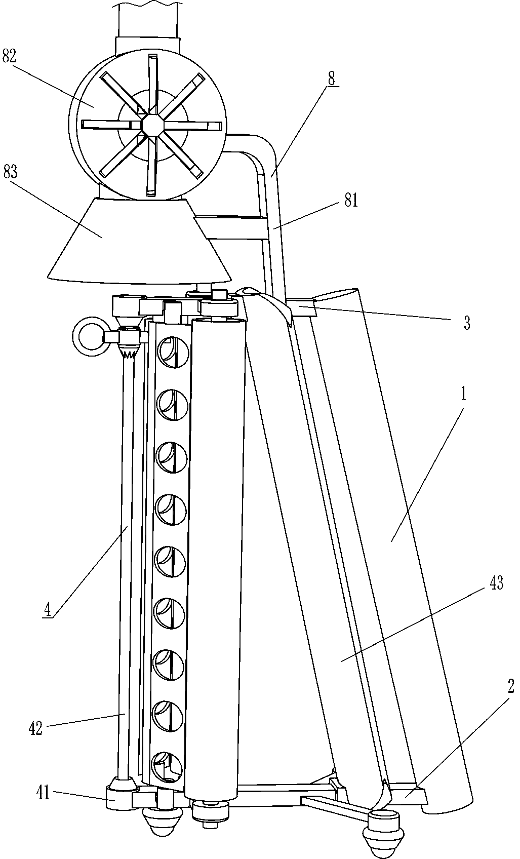
[0023] see Figure 1-Figure 3 , a foam board cutting equipment, including a handle 1, a mounting rod 2, a fixed rod 3, a melting and cutting mechanism 4 and a cleaning mechanism 5, the lower part of the left side of the handle 1 is fixedly connected with the installation rod 2, and the upper part of the left side of the handle 1 is fixed A fixed rod 3 is connected, a melting and cutting mechanism 4 is arranged between the fixing rod 3 and the installation rod 2 , and a cleaning mechanism 5 is arranged between the fixing rod 3 and the melting and cutting mechanism 4 .

[0024] The melting and cutting mechanism 4 includes a heat insulating block 41, a heating wire 42 and a protective plate 43, and a protective plate 43 is embedded between the right side of the top of the mounting rod 2 and the right part of the fixed rod 3, and the left end of the fixed rod 3 is connected to the mounting rod 2 A thermal insulation block 41 is fixedly connected to the left end, and a heating wire...

Embodiment 2

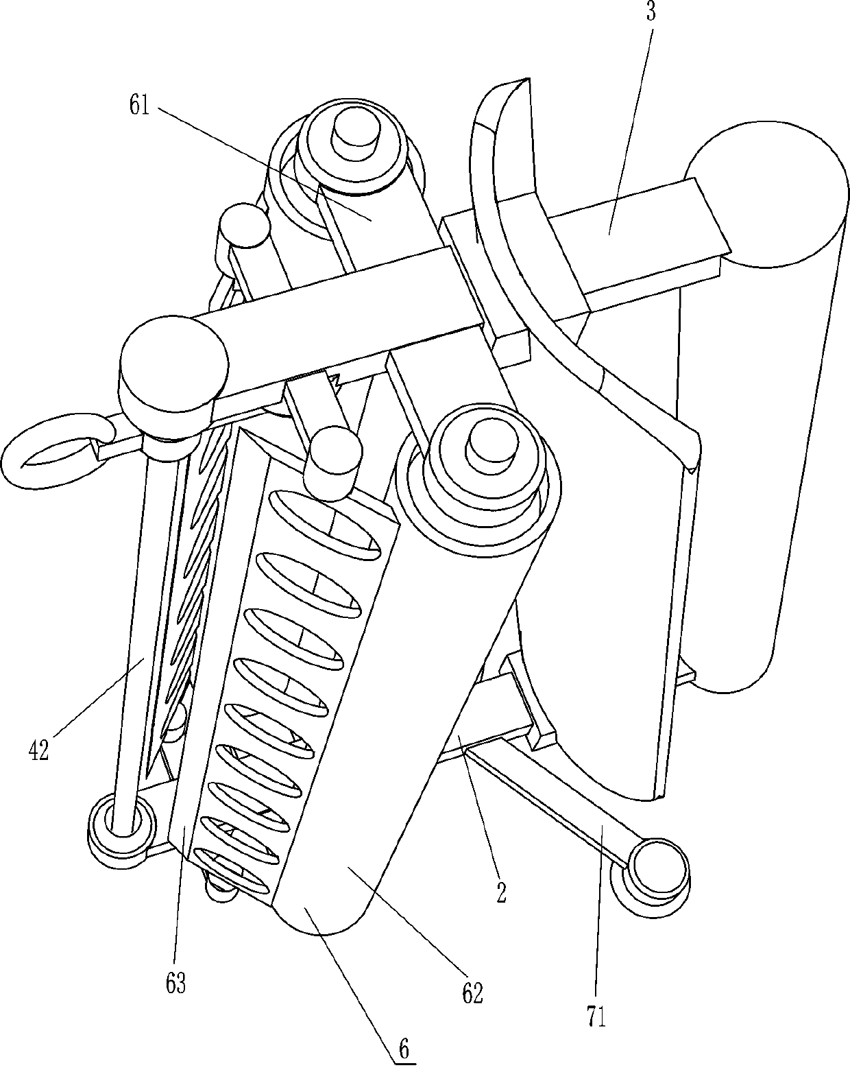
[0030] see figure 1 , Figure 4 and Figure 5Compared with Embodiment 1, the main difference of this embodiment is that in this embodiment, a flaring mechanism 6 is also included. The flaring mechanism 6 includes a fixed frame 61, a roller 62 and a guide plate 63, and the left side of the front and rear sides of the fixed rod 3 The left part of the front and rear sides of the installation rod 2 is fixedly connected with a fixed frame 61, and the roller 62 is rotatably connected between the fixed frame 61 of the upper and lower sides of the front and the fixed frame 61 of the upper and lower sides of the rear, and the front side of the fixed rod 3 A guide plate 63 is fixedly connected between the left side and the left side of the front side of the installation rod 2 , and a guide plate 63 is also fixedly connected between the left side of the rear side of the fixed rod 3 and the left side of the rear side of the installation rod 2 .

[0031] Also comprise auxiliary mobile me...


PUM


Abstract

The invention relates to cutting equipment, in particular to foam board cutting equipment. The technical problem is how to design foam board cutting equipment which can extract out poisonous gas, doesnot influence human body health and can prevent hands from being scalded by cut foam boards. The foam board cutting equipment comprises a handle, and a fusion cutting mechanism. A mounting rod is fixedly connected to the edge position of one side of the handle, and a fixed rod is fixedly connected to the edge position of the other side of the handle. The fusion cutting mechanism is mounted between the fixed rod and the mounting rod and is used for cutting foam boards. According to the foam board cutting equipment, an electric heating wire is started, the handle is held, the electric heating wire is moved through the fixed rod, the mounting rod and heat insulation blocks to be in contact with foam boards, the electric heating wire cuts foam boards, a protection board protects the hands ofpeople, and therefore the cut foam boards can be prevented from scalding the hands of people.

Description

technical field [0001] The invention relates to a cutting device, in particular to a foam board cutting device. Background technique [0002] Polystyrene foam board - also known as foam board, EPS board is made of expandable polystyrene beads containing volatile liquid foaming agent. It is a white object heated and formed in a mold after heating and pre-expanding. The structural characteristics of holes are mainly used for building walls, roof insulation, composite board insulation, cold storage, air conditioning, vehicle, ship insulation, floor heating, decoration and engraving, etc. For a large piece, the foam board needs to be cut for subsequent use. [0003] Existing cutting devices, such as the Chinese patent whose patent notification number is CN207172291U discloses a foam board cutting device, which includes two connected cutting support rods, a rotatable wire rack and heating wire arranged on the cutting support rods, The two ends of the heating wire are respective...

Claims


Application Information

Patent Timeline
Patent Type & Authority Applications(China)
IPC IPC(8): B26F3/12B26D7/22B26D7/00B08B15/04B26D7/08
CPCB26F3/12B26D7/22B26D7/00B08B15/04B26D7/08Y02W30/62
Inventor 伍尚齐
Owner 南通科橙机器人有限公司
Why Eureka
Try Eureka