
Taper guiding mechanism for injection mold

A guiding mechanism and injection mold technology, applied in the field of injection molds, can solve the problems of product quality such as gaps left in the air and drums, rough taper processing, sticky and white scraps, etc., to improve the consumption of taper manual adjustment and facilitate taper pressure And angular distance, the effect of pass rate improvement

Inactive Publication Date: 2020-08-14
黄淑珠
View PDF9 Cites 0 Cited by
  • Summary
  • Abstract
  • Description
  • Claims
  • Application Information

AI Technical Summary

Problems solved by technology

[0004] In view of the deficiencies in the prior art, the purpose of the present invention is to provide a taper guide mechanism for injection molds to solve the problem that in injection molds, the slope taper of mold sliding pressure is an important corner between the parting surface of the hammer and the mold groove. Adjusting the size, the taper guide of the mold sliding pressure is too wide, which will cause the injection molding to leave a seam and squeeze the overflowing material, so that the overflowing edge pieces need to be cut in the later stage to waste material costs, and the overflowing viscous material surface is bonded to the upper and lower parts of the parting surface The two ends lead to the phenomenon of sticking, pressing and whitening of the leftover material, which makes the taper processing of the mold on the leftover material very rough, resulting in gaps in the product quality, resulting in unqualified batch production, and also affecting the output of the mold after injection molding. The problem of model efficiency

Method used

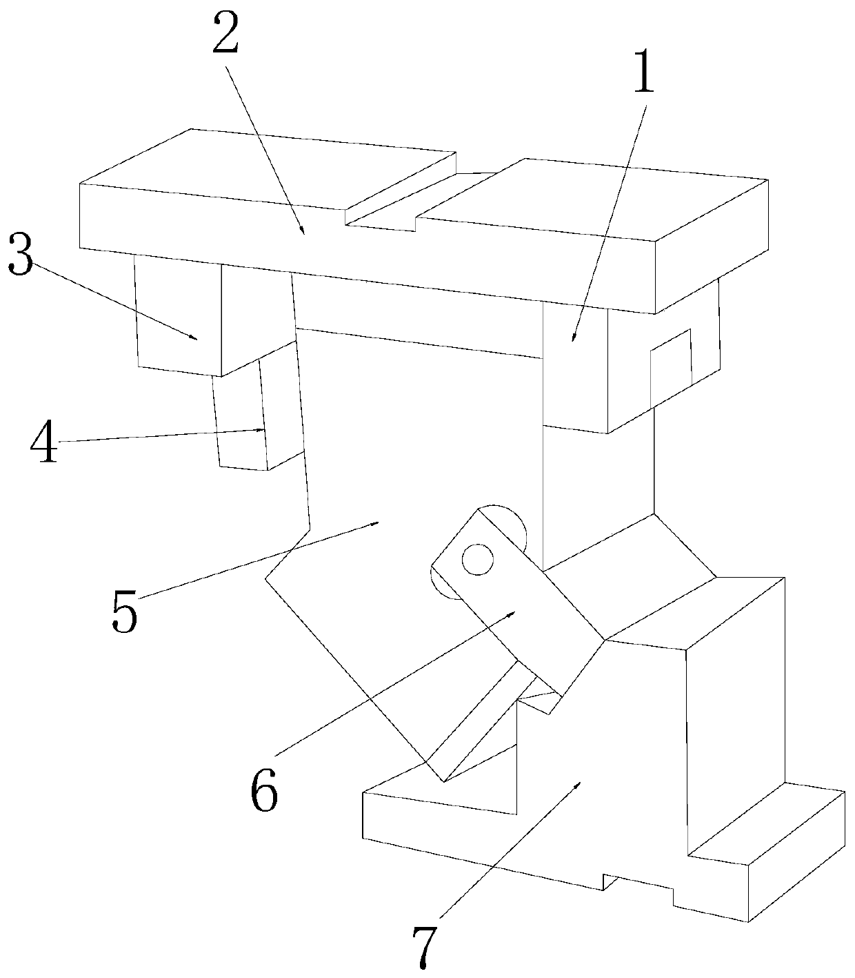

Image

  • Taper guiding mechanism for injection mold
  • Taper guiding mechanism for injection mold
  • Taper guiding mechanism for injection mold

Examples


Embodiment 1

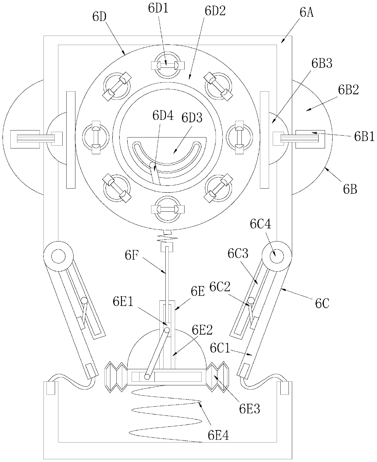
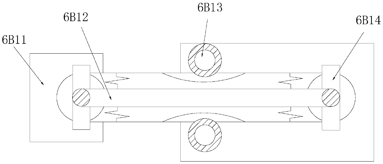
[0033] see Figure 1-Figure 6 , the present invention provides a taper guide mechanism for an injection mold, the structure of which includes: a bayonet plug block 1, a parting surface support plate 2, a trachea slot 3, an insert plate 4, a card angle taper frame 5, and a taper angle guide wheel Groove 6, formwork groove column block 7, described cone angle guide wheel groove 6 and card angle taper frame 5 are fastened together and are on the same vertical plane, and described cone angle guide wheel groove 6 is inserted in formwork groove column block 7, the trachea slot 3 is nested on the top of the insert plate 4 and is on the same vertical plane, and the trachea slot 3 and the bayonet socket block 1 are respectively inserted into the parting surface support The left and right lower corners of the plate 2 are parallel to each other, the card angle taper frame 5 is close to the bottom surface of the bayonet plug block 1 and is on the same vertical plane, and the cone angle gu...

Embodiment 2

[0040] see Figure 1-Figure 6 , the present invention provides an injection mold taper guide mechanism, which is the same as in Embodiment 1 in other respects, except that:

[0041] see figure 2 , the lifting and pushing bracket seat 6E is composed of a lifting column block 6E1, a cross track seat 6E2, a louver support groove 6E3, and a torsion spring wire 6E4. The lifting column block 6E1 and the cross track seat 6E2 adopt a clearance fit, and the The cross track seat 6E2 is mechanically connected with the torsion spring wire 6E4, and the said louver support groove 6E3 is provided with two and respectively installed on the left and right sides of the cross track seat 6E2, and the left and right ends of the cross track seat 6E2 are limited by the louver support groove 6E3. The elastic pressure cone angle slope forms an overall horizontal and vertical inner frame top support effect, ensuring the stability of the limit rotation and the lifting angle of the plate.

[0042] see...


PUM


Abstract

The invention discloses a taper guiding mechanism for an injection mold. The taper guiding mechanism structurally comprises a bayonet lock inserting block, a parting surface supporting plate, an air pipe inserting groove, an inserting piece plate, a clamping angle taper frame, a taper angle guide wheel groove and a mold plate groove column block. According to the taper guiding mechanism, the mutual cooperation between the clamping angle taper frame and the taper angle guide wheel groove is applied, a wheel groove shell body is occluded through the clamping angle taper frame, and an angle adjusting sliding pressing frame with the upper end face and the lower end face bearing pressure is erected at the bottom of a round petal liquid pipe base of the parting surface of a taper side position mold, so that the round petal liquid pipe base forms the effect of being matched with a left wheel correcting disc for balance correction, and then a swing rod frame wheel groove is matched for liftingand rotating, so that the high-low-position taper obtains the seamless splicing tight attaching fine adjustment effect, the taper is guided to be matched with an upper parting surface cover plate anda lower parting surface cover plate of the mold for sliding pressing, pasting and sealing operation on an injection molding inner mold groove is formed, the taper manual adjustment consumption degreeof mold processing is improved, the preciseness of automatic adaptive fine adjustment of a rack is improved, the taper pressure and the angular distance make accurate conveniently, and the qualifiedrate of batch injection molding processing is increased.

Description

technical field [0001] The invention relates to a taper guide mechanism of an injection mold, which belongs to the field of injection molds. Background technique [0002] Injection molds are commonly used equipment in the preparation of conventional plastic molds. It is convenient to use liquid plastic liquid to pour mold grooves for cooling and molding, and the pressure density allows the taper in the mold to reach a certain qualified angle, which is convenient for plastic parts after die-casting. The basic mass production level improves the labor-saving effect of mechanical processing. The shortcomings of the current technology that need to be optimized are: [0003] In the injection mold, the taper of the inclined surface of the mold sliding pressure is an important corner adjustment dimension between the direct hammering parting surface and the molding mold groove. If the taper guide of the mold sliding pressure is too wide, it will cause the injection molding to leave a...

Claims


Application Information

Patent Timeline
IPC IPC(8): B29C45/26B29C45/80
CPCB29C45/2606B29C45/80
Inventor 黄淑珠
Owner 黄淑珠
Learn More