Frame of sewing machine

A sewing machine and frame technology, which is applied in the field of sewing machine frames, can solve the problems of inconvenient movement, difficulty in placing the sewing machine stably, and small contact area.

Active Publication Date: 2020-08-14
JACK SEWING MASCH CO LTD
View PDF11 Cites 8 Cited by
  • Summary
  • Abstract
  • Description
  • Claims
  • Application Information

AI Technical Summary

Problems solved by technology

But above-mentioned two kinds of schemes all have deficiencies: for example when four corners are all supported by foot cup, although the height of foot cup is adjustable, the adaptability to the ground is better, but the coefficient of friction between foot cup and ground is bigger , and the overall size of the sewing machine is relatively large. In addition, the overall weight of the sewing machine is generally about 80Kg. At this time, if you want to move the sewing machine, you only need to lift it up by multiple people or carry it by machine, which is time-consuming and labor-intensive. The efficiency is low; It is relatively easy to move the sewing machine supported by two foot cups, but the height of the casters cannot be adjusted, so the adaptability of the frame to the ground is very poor, and the line-surface contact between the casters and the ground, contact The small area leads to small frictional force. The above-mentioned shortcomings make it difficult to place the sewing machine with this structure stably, which affects the sewing effect.
[0006] The sewing machine frame in the above patent document is supported by four foot cups, which is inconvenient to move, and the adjustability and versatility are poor, and the height of the platen installed on the frame cannot be adjusted, which affects the convenience and comfort of use

Method used


Image

  • Frame of sewing machine
  • Frame of sewing machine
  • Frame of sewing machine

Examples


Embodiment Construction

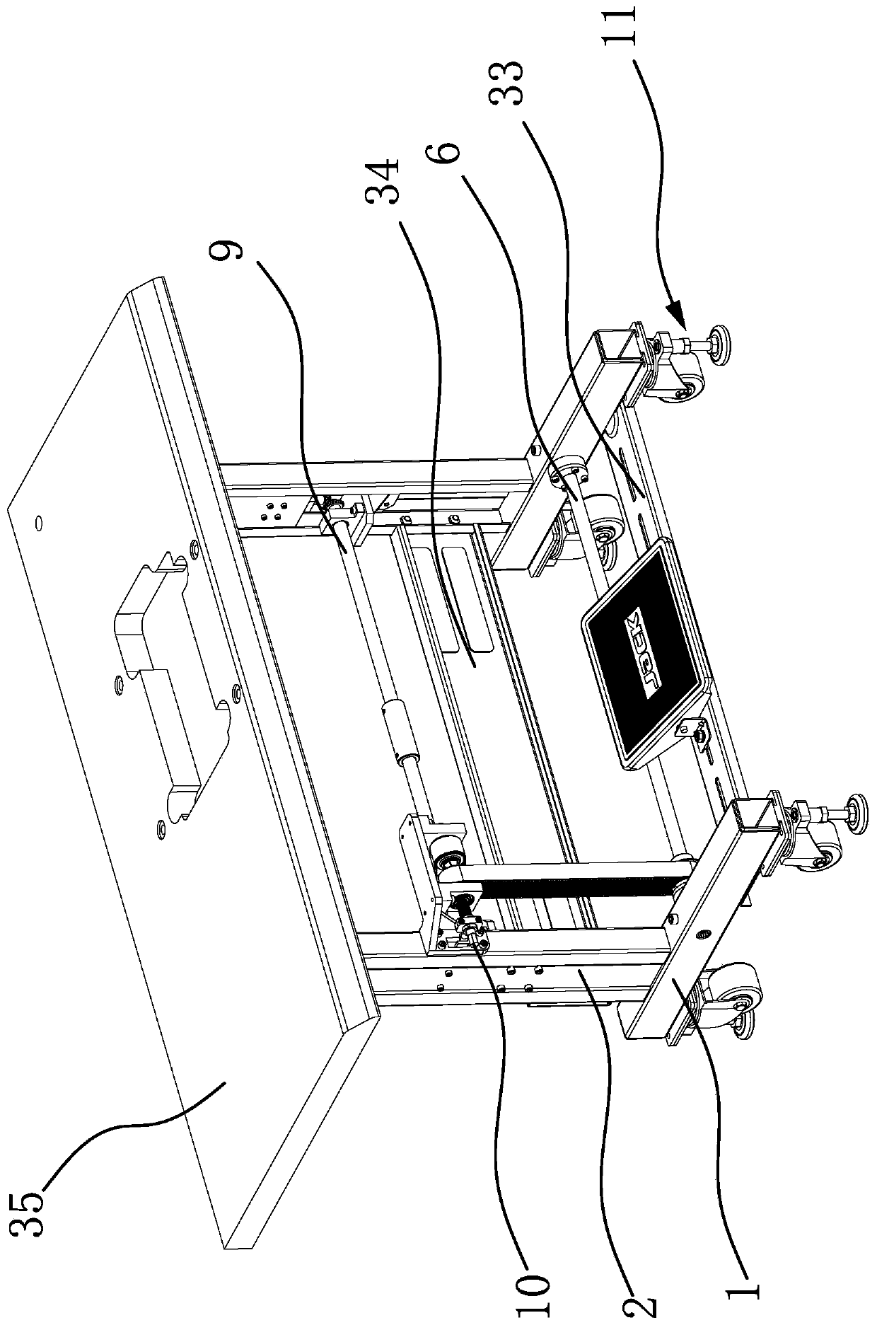
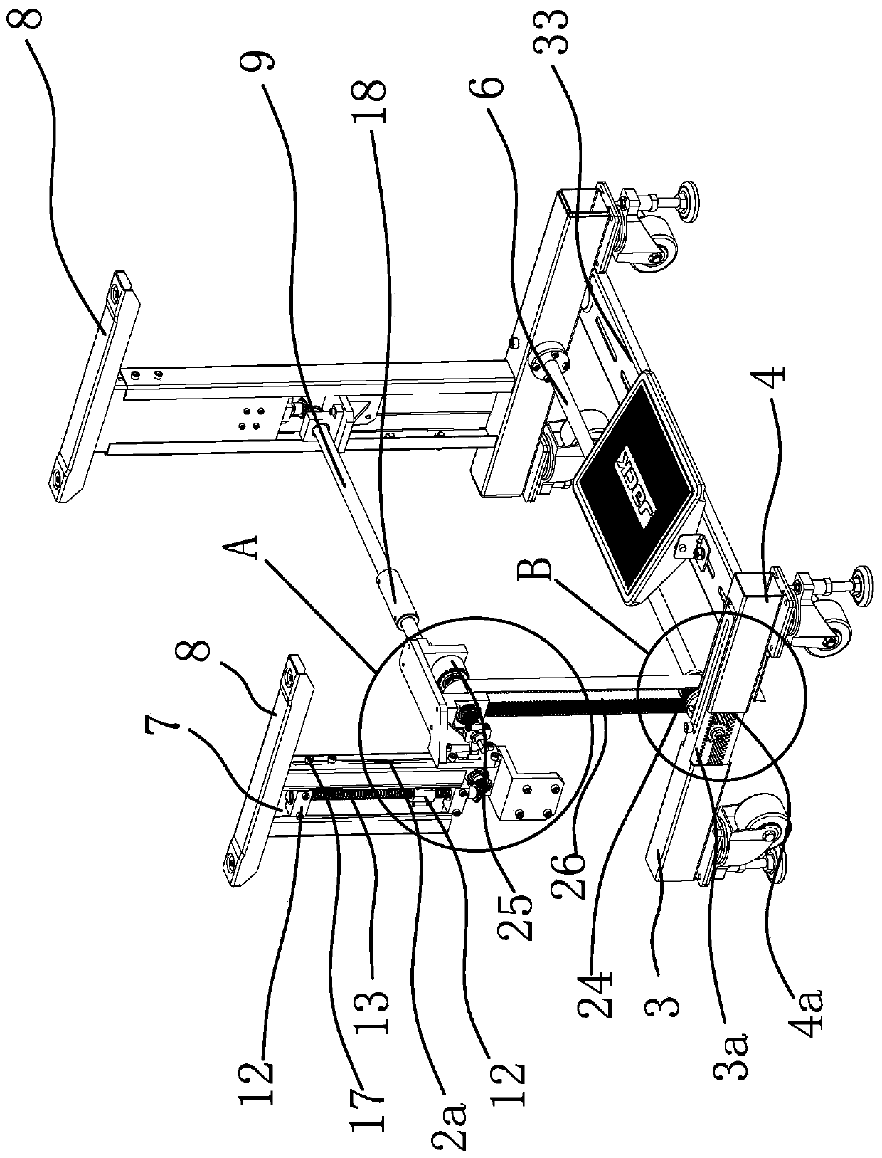
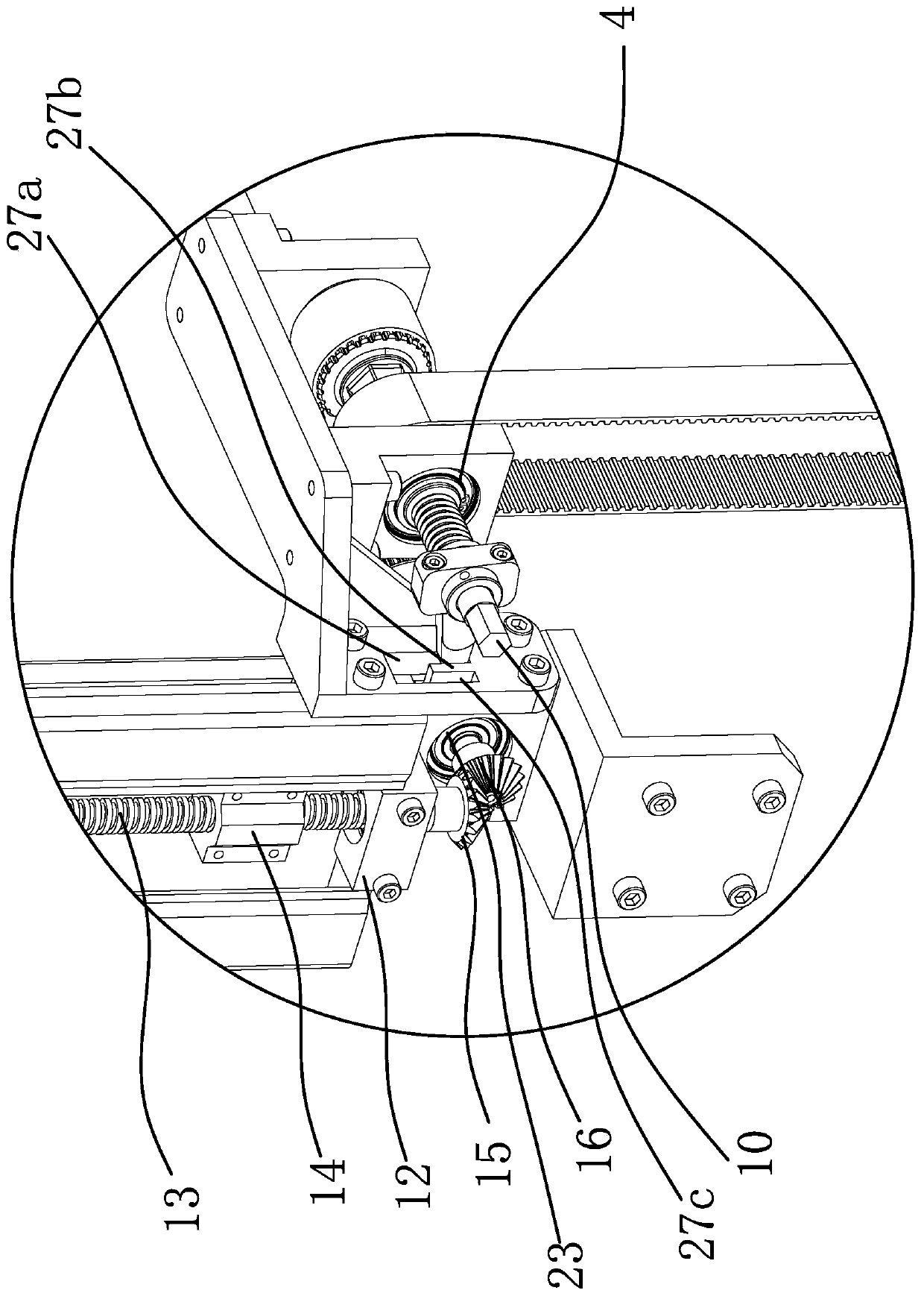
[0039] Such as Figure 1 to Figure 7 As shown, the frame of the sewing machine includes two tubular bases 1 vertically spaced apart, each base 1 is vertically fixed with a column 2, and the two ends of each base 1 are respectively movably inserted with an upper support tube 3 and Lower support tube 4, the lower side of the lower support tube 4 has a lower rack 4a extending towards the inside of the base 1, and the upper side of the upper support tube 3 has an upper rack 3a extending towards the inside of the base 1; the upper rack 3a and the lower teeth The bar 4a is arranged oppositely and is provided with the meshing gear 5 that can simultaneously drive the upper rack 3a and the lower rack 4a to move longitudinally between the two, and the lower transmission shaft 6 is connected on the meshing gear 5; The upper end of the lifting pillar 7 is provided with a supporting plate 8, and the lower part of the lifting pillar 7 is provided with an upper transmission shaft 9 that can ...


PUM


Abstract

The invention provides a frame of a sewing machine, and belongs to the technical field of sewing machine accessories. The technical problems that the frame structure of an existing sewing machine is inconvenient to move, poor in adaptability and the like are solved. The frame comprises two tubular bases, each base is vertically and fixedly provided with a stand column, an upper supporting pipe anda lower supporting pipe are movably inserted to the two ends of each base correspondingly, the lower side of each lower supporting pipe is provided with a lower rack, and the upper side of each uppersupporting pipe is provided with an upper rack; a meshing gear is arranged between each upper rack and the corresponding lower rack, and a lower transmission shaft is connected to the meshing gears;a vertical lifting support column is slidably arranged on each stand column, and an upper transmission shaft capable of driving each lifting support column to move up and down is arranged below the lifting support column; a driving shaft capable of driving the corresponding upper transmission shaft and a lower transmission shaft to rotate respectively is further arranged on each stand column; andsupporting foot assemblies are mounted at the bottoms of the outer ends of the upper supporting pipes and the lower supporting pipes. The frame is convenient to move; and the distance between the supporting foot assemblies and the height of a table plate can be adjusted, and the adaptability is strong.

Description

technical field [0001] The invention belongs to the technical field of sewing machine accessories, and relates to a sewing machine frame. Background technique [0002] Usually a complete set of sewing machine is mainly composed of sewing machine, table top, frame and other accessories. The frame of sewing machine is an indispensable part in the sewing machine as the carrier of the table top and sewing machine. The frame of the sewing machine is generally supported by the foot cups installed at each of the four corners. At the same time, for the convenience of movement, some frames are composed of two casters and two foot cups, so that the sewing machine can be easily moved only by lifting one side. But above-mentioned two kinds of schemes all have deficiencies: for example when four corners are all supported by foot cup, although the height of foot cup is adjustable, the adaptability to the ground is better, but the coefficient of friction between foot cup and ground is bigg...

Claims


Application Information

Patent Timeline
Patent Type & Authority Applications(China)
IPC IPC(8): D05B75/00
CPCD05B75/00
Inventor 蔡炳清黄小青祝书伟徐智张鑫媛
Owner JACK SEWING MASCH CO LTD
Why Eureka
Try Eureka