Road surface drainage well self-regulated-controlled for cleaning

A self-regulating, drainage well technology, applied to drainage structures, waterway systems, water supply devices, etc., can solve the problems of poor drainage and difficult cleaning of drainage wells, and achieve the effects of preventing injuries, increasing drainage, and being easy to use

Active Publication Date: 2020-08-14
如皋市规划建筑设计院有限公司
View PDF7 Cites 2 Cited by
  • Summary
  • Abstract
  • Description
  • Claims
  • Application Information

AI Technical Summary

Problems solved by technology

[0005] The purpose of the present invention is to provide a self-regulating and clean pavement drainage well with intelligent adjustment of

Method used


Image

  • Road surface drainage well self-regulated-controlled for cleaning
  • Road surface drainage well self-regulated-controlled for cleaning
  • Road surface drainage well self-regulated-controlled for cleaning

Examples


Embodiment 1

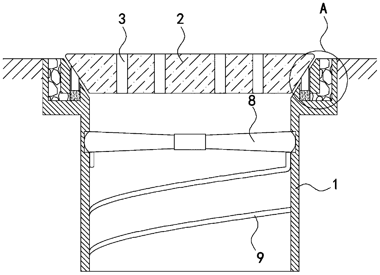
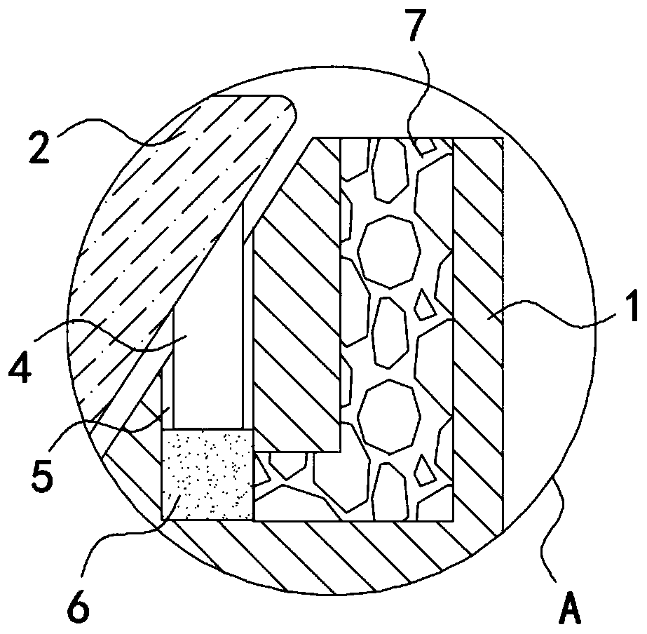
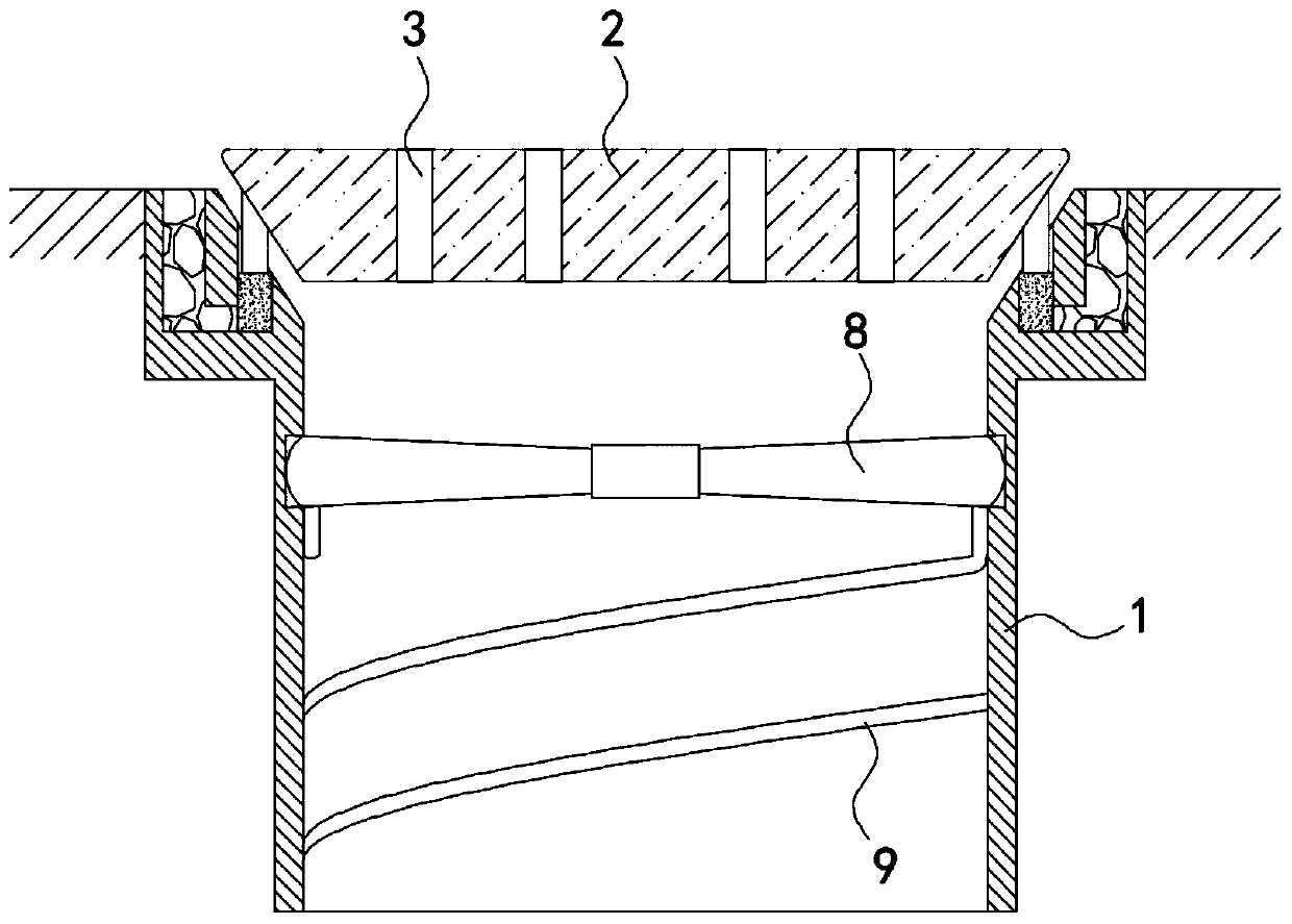
[0022] Such as Figure 1-4 As shown, a self-regulating and clean road drainage well includes a well body 1 and a well cover 2 arranged above the well body 1. The surface of the well cover 2 is provided with a plurality of equally spaced strip drainage holes 3, and the well cover 2 is inverted The upper opening of the well body 1 is in the shape of a truncated cone, and it is arranged in a horn-like shape and is attached to the 2 peripheral side walls of the well cover. A plurality of support bars 4 arranged in an annular array are fixedly installed on the peripheral side walls of the well cover 2, and the upper end of the well body 1 is provided There are a plurality of strip grooves 5 matching the support bar 4, the lower end of the support bar 4 extends into the strip groove 5, the bottom of the strip groove 5 is provided with a water-absorbing expansion block 6, and the upper surface of the well body 1 is provided with a water-permeable layer 7. The lower end of the water-pe...

Embodiment 2

[0030] Such as Figure 5 As shown, the difference between this embodiment and Embodiment 1 is that the impeller 8 includes a gear 10 and fan blades 11 fixedly mounted on both sides of the gear 10. The two fan blades 11 are separated from each other on the side of the shaft 1 The wall is rotatably connected, and the bottom surface of the manhole cover 2 is rotatably connected with a vertical rack 12 which meshes with the gear 10.

[0031] In this embodiment, when the road area has a large amount of water, when the support bar 4 pushes the manhole cover 2 upward, it drives the rack 12 to move upward, and the gear meshed with it rotates 90°, that is, the fan blade 11 turns 90° along its axis. °, at this time, under the impact of the water flow, the force direction of the fan blade 11 changes, the impeller 8 rotates in the reverse direction, and then drives the scrubbing strip 9 to rotate in the reverse direction. This structure allows the scrubbing strip 9 to reciprocate in the well ...


PUM


Abstract

The invention belongs to the field of sponge city construction, and particularly relates to a road surface drainage well self-regulated-controlled for cleaning. The road surface drainage well comprises a well body and a well lid arranged above the well body. Multiple strip-shaped drainage holes arranged at equal intervals are formed in the surface of the well lid, the well lid is in an inverted circular truncated cone shape, the upper face of the well body is open, the upper face of the well body is in a horn shape and is attached to the peripheral wall of the well lid, multiple annularly-arrayed supporting strips are fixedly mounted on the peripheral wall of the well lid, multiple strip-shaped grooves matched with the supporting strips are formed in the upper end of the well body, the lower ends of the supporting strips stretch into the strip-shaped grooves, water swelling blocks are arranged at the bottoms of the strip-shaped grooves, water absorbing cotton lines are arranged in thestrip-shaped grooves, and one ends of the water absorbing cotton lines are wound around the water swelling blocks. When the precipitation is large, the well lid can be automatically propped up, the drainage amount of the drainage well is increased, meanwhile, water currents drive scrape-washing strips to rotate, impurities and dirt attached to the interior of the well body are scraped away, and normal drainage of the drainage well is prevented from being affected.

Description

Technical field [0001] The invention belongs to the field of sponge city construction, and particularly relates to a self-regulating and clean road drainage well. Background technique [0002] Drainage wells are mostly set up on both sides of the road or street to drain rainwater in time and prevent road surface water. When there is a lot of rain and heavy rainfall, if the precipitation on the street is not removed in time, it will have an adverse impact on urban traffic. In the construction of sponge cities, the rational use of drainage wells plays a key role in the infiltration, purification and utilization of rainwater. [0003] Traditional drainage wells are mostly equipped with multiple drainage holes on the manhole cover for the drainage of rainwater. When the amount of rainwater is large, or the road area has a lot of water, and the drainage of the drainage holes is difficult to meet the drainage needs, the drainage must be manually drained. The cover of the well is opened....

Claims


Application Information

Patent Timeline
IPC IPC(8): E03F5/04E03F5/06
CPCE03F5/0401E03F5/0402E03F5/06E03F2005/068
Inventor 官春玲张琼
Owner 如皋市规划建筑设计院有限公司
Why Eureka
Try Eureka