A self-regulating and cleaning pavement drainage well

A self-regulating, drainage well technology, applied to drainage structures, waterway systems, water supply devices, etc., can solve the problems of poor drainage effect and difficult cleaning of drainage wells, so as to avoid affecting urban traffic, increase drainage, and prevent dangerous accidents Effect

Active Publication Date: 2021-05-04
如皋市规划建筑设计院有限公司
View PDF7 Cites 0 Cited by
  • Summary
  • Abstract
  • Description
  • Claims
  • Application Information

AI Technical Summary

Problems solved by technology

[0005] The purpose of the present invention is to provide a self-regulating and clean pavement drainage well with intelligent adjustment of drainage speed and automatic cleaning for the problems of poor drainage effect and difficult cleaning of the above-mentioned drainage wells

Method used


Image

  • A self-regulating and cleaning pavement drainage well
  • A self-regulating and cleaning pavement drainage well
  • A self-regulating and cleaning pavement drainage well

Examples


Embodiment 1

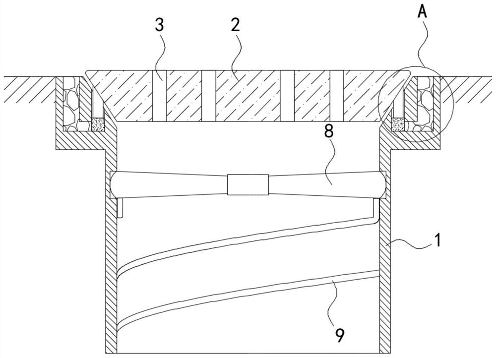
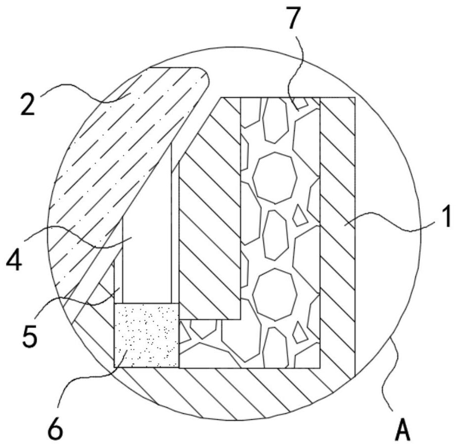
[0022] Such as Figure 1-4 As shown, a self-regulating and clean pavement drainage well includes a well body 1 and a well cover 2 arranged above the well body 1. The surface of the well cover 2 is provided with a plurality of equidistant strip drain holes 3, and the well cover 2 is inverted. The top of the well body 1 is set in the shape of a circular platform, and the upper opening of the well body 1 is trumpet-shaped and is set close to the side walls around the well cover 2. A plurality of support bars 4 arranged in an annular array are fixedly installed on the side walls of the well cover 2, and the upper end of the well body 1 is set. There are a plurality of bar-shaped grooves 5 matched with the support bar 4, the lower end of the support bar 4 extends into the bar-shaped groove 5, the bottom of the bar-shaped groove 5 is provided with a water-absorbing expansion block 6, and the upper surface of the well body 1 is provided with a water-permeable layer 7. The lower end o...

Embodiment 2

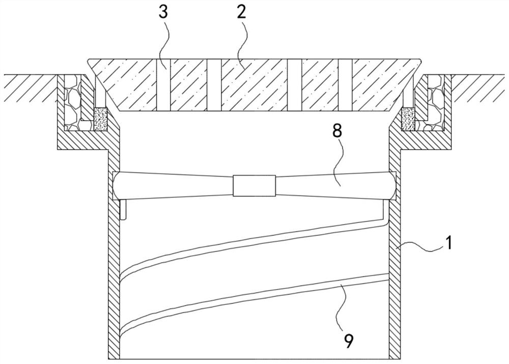
[0030] Such as Figure 5 As shown, the difference between this embodiment and Embodiment 1 is that the impeller 8 includes a gear 10 and fan blades 11 fixedly installed on both sides of the gear 10, and the ends of the two fan blades 11 that are far away from each other are connected to the side of the well body 1. The wall is rotatably connected, and the bottom surface of the well cover 2 is rotatably connected with a vertical rack 12, and the rack 12 is meshed with the gear 10.

[0031] In this embodiment, when there is a lot of water in the road area, when the support bar 4 pushes the manhole cover 2 to move upward, it drives the rack 12 to move upward, and the gear meshed with it rotates 90°, that is, the fan blade 11 turns 90° along its axis. °, then under the impact of the water flow, the force direction of the fan blade 11 changes, and the impeller 8 rotates in the opposite direction, and then drives the scraping strip 9 to rotate in the opposite direction. This structu...


PUM


Abstract

The invention belongs to the field of sponge city construction, and in particular relates to a self-regulating and clean pavement drainage well, which includes a well body and a well cover arranged above the well body, and the surface of the well cover is provided with a plurality of strip-shaped drainage holes arranged equidistantly , the well cover is arranged in the shape of an inverted circular platform, and the opening above the well body is in the shape of a trumpet and is arranged close to the side wall of the well cover, and a plurality of support bars arranged in an annular array are fixedly installed on the side wall of the well cover. The upper end of the well body is provided with a plurality of bar-shaped grooves matching the support bars, the lower end of the support bars extends into the bar-shaped grooves, the bottom of the bar-shaped grooves is provided with a water-absorbing expansion block, and the bar-shaped grooves are provided with There is a water-absorbing cotton thread, and one end of the water-absorbing cotton thread is wound outside the water-absorbing expansion block. The invention can automatically prop up the well cover when the rainfall is large, increasing the drainage of the drainage well, and at the same time, the water flow drives the scraping strip to rotate, scraping off the impurities and sludge attached to the well body, and avoiding the normal drainage of the drainage well make an impact.

Description

technical field [0001] The invention belongs to the field of sponge city construction, and in particular relates to a self-regulating and cleaning road drainage well. Background technique [0002] Most of the drainage wells are set on the road or on both sides of the street to drain rainwater in time and prevent the road from accumulating water. When there is a lot of rain and the amount of rainfall is large, if the precipitation on the street is not removed in time, it will have a negative impact on urban traffic. In the construction of sponge cities, the rational use of drainage wells plays a key role in the infiltration, purification and utilization of rainwater. [0003] Most of the traditional drainage wells are provided with multiple drainage holes on the well cover for the drainage of rainwater. When the amount of rainwater is large, or there is a lot of water on the road, and the drainage of the drainage holes is difficult to meet the drainage needs, it is necessary ...

Claims


Application Information

Patent Timeline
Patent Type & Authority Patents(China)
IPC IPC(8): E03F5/04E03F5/06
CPCE03F5/0401E03F5/0402E03F5/06E03F2005/068
Inventor 官春玲张琼
Owner 如皋市规划建筑设计院有限公司
Why Eureka
Try Eureka