Stereoscopic parking equipment rack structure
A three-dimensional parking and equipment layer technology, which is applied to parking buildings, electric vehicles, vehicle energy storage, etc., can solve the problems of high processing cost and poor bending resistance of pipe fittings, and achieve convenient processing, improve the rigidity of the shelf, The effect of good bending support ability
- Summary
- Abstract
- Description
- Claims
- Application Information
AI Technical Summary
Problems solved by technology
Method used
Image

Examples
Embodiment 1
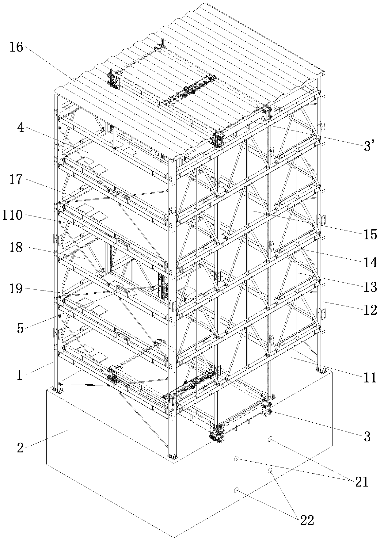
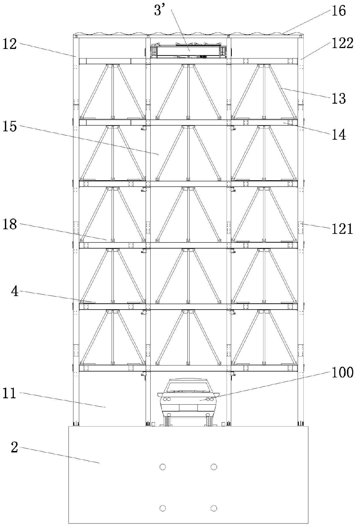
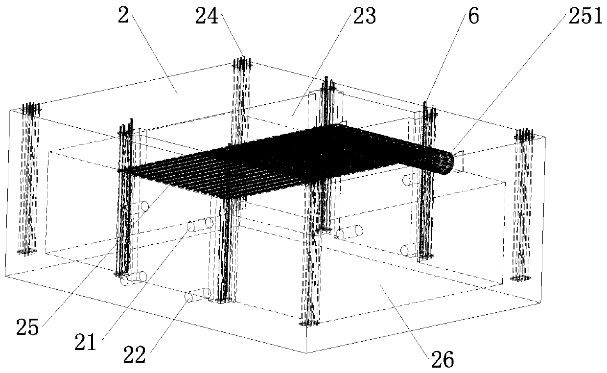
[0050] Embodiment one, see Figure 1 to Figure 24 Shown, a kind of three-dimensional parking equipment with fire extinguishing function, comprises layer frame 1, vehicle-carrying board 4 and elevating frame, layer frame 1 is provided with the upper floor parking space 18 of more than one layer, and layer frame 1 corresponds to the upper layer parking space 18 and is arranged There is a moving channel 15, the lower end of the moving channel 15 leads to the lower part of the shelf 1, and the lift frame is arranged on the moving channel 15, and is used to control the movement of the vehicle-carrying plate 4 between the upper parking space 18 and the moving channel 15 , also includes a fire extinguishing pit 2, the fire extinguishing pit 2 is arranged at the bottom of the shelf 1, an isolation cavity 26 is provided inside the fire extinguishing pit 2, and a top opening 23 is provided on the isolation cavity 26, and the top opening 23 is opposite to the bottom of the moving vehicle ...
Embodiment 2
[0106] Embodiment two, the difference with embodiment one is: see Figure 27 to Figure 32 As shown, the top surface of the lifting frame (taking the main lifting frame 3 as an example) is provided with a push-pull mechanism on the lifting frame, and the push-pull mechanism is used to pull the vehicle-carrying plate 4 in the upper parking space to the lifting frame, and Push the car-loading plate 4 on the lifting frame into the upper parking space.
[0107] The push-pull mechanism is provided with two sets, one set acts on the vehicle-carrying plate 4 on the left side, and the other set acts on the vehicle-carrying plate 4 on the right side. If there is only one upper parking space, only the corresponding set of push-pull mechanism needs to be reserved. Institutions will do.
[0108] The push-pull mechanism acting on the left side vehicle-loading plate 4 comprises a left tension motor, a left tension drive gear 301, a left tension rack 302, a left pull hook 303, a left thrust ...
PUM
| Property | Measurement | Unit |
|---|---|---|
| Depth | aaaaa | aaaaa |
Abstract
Description
Claims
Application Information
 - R&D
- Intellectual Property
- Life Sciences
- Materials
- Tech Scout
- Unparalleled Data Quality
- Higher Quality Content
- 60% Fewer Hallucinations
Browse by: Latest US Patents, China's latest patents, Technical Efficacy Thesaurus, Application Domain, Technology Topic, Popular Technical Reports.
© 2025 PatSnap. All rights reserved.Legal|Privacy policy|Modern Slavery Act Transparency Statement|Sitemap|About US| Contact US: help@patsnap.com