Mining rock drill

A rock drill and mining technology, applied in the field of mining machinery, can solve problems affecting workers' operating vision and operating errors, and achieve the effect of ensuring the operating vision, ensuring operation, and reducing drift

Inactive Publication Date: 2020-08-14
吴锦丁
View PDF11 Cites 0 Cited by
  • Summary
  • Abstract
  • Description
  • Claims
  • Application Information

AI Technical Summary

Problems solved by technology

[0005] Aiming at the deficiencies in the prior art, the purpose of the present invention is to provide a rock drill for mines, to solve the problem of the prior art because the mine is open everywhere and all sides may be affected by the wind. The movement will cause the drilled dust to flutter irregularly under the influence of the wind. At this time, the dust will float to the front of the workers with the wind, which will affect the workers' operating vision and cause operational errors.

Method used


Image

  • Mining rock drill
  • Mining rock drill
  • Mining rock drill

Examples


Embodiment 1

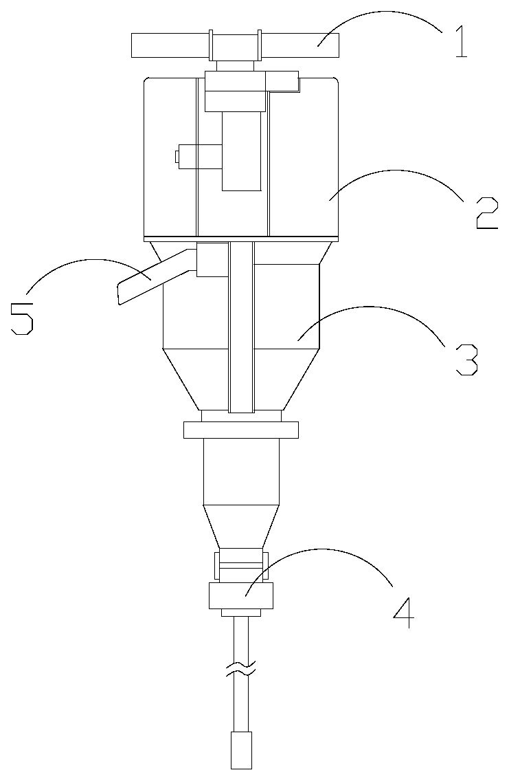
[0030] Example 1: Please refer to Figure 1-Figure 6 , the specific embodiments of the present invention are as follows:

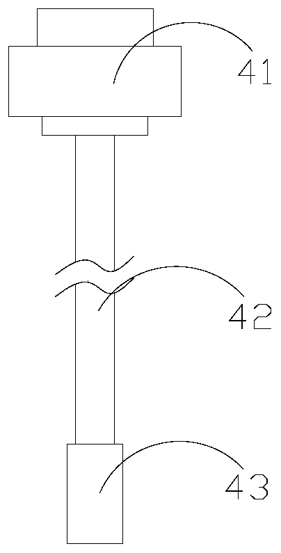
[0031] Its structure includes a handle 1, a machine head 2, a drive box 3, a rock drilling mechanism 4, and a side handle 5. The handle 1 is horizontally installed on the upper end of the machine head 2 and is mechanically connected. The drive box 3 is vertically installed on the The lower end of the machine head 2 is engaged with each other, the rock drilling mechanism 4 is vertically fixed on the lower end of the driving box 3 and is located on the same center line, the side handle 5 is installed on the side end of the driving box 3 and is fixedly connected; the rock drilling mechanism 4 includes a fixing seat 41, a steel brazing structure 42, and an impact head 43. The steel brazing structure 42 is vertically embedded and installed inside the fixing seat 41 and is mechanically connected. The impact head 43 is sleeved on the outside of the steel brazing ...

Embodiment 2

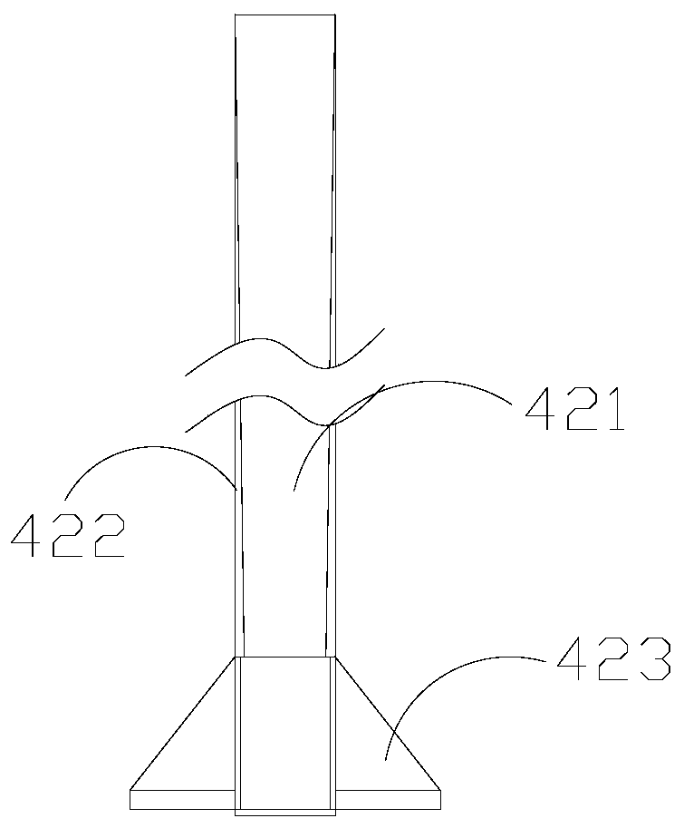
[0038] Example 2: Please refer to Figure 4 , Figure 7-Figure 10 , the specific embodiments of the present invention are as follows:

[0039] The blocking structure 423 includes a sliding structure 23a, a movable structure 23b, and an inner groove 23c. The sliding structure 23a is horizontally installed on the lower end of the movable structure 23b and is located on the same axis. The inner groove 23c runs through the inner side of the sliding structure 23a and is integrated. The movable structure 23b is sleeved on the outside of the steel brazing 421 and the inner groove 23c surrounds the steel brazing 421.

[0040] refer to Figure 7-Figure 8 The movable structure 23b includes a sliding seat b1, an installation groove b2, an inner chute b3, a support structure b4, and a dust outlet b5. The installation groove b2 is set inside the sliding seat b1 and is an integrated structure. The inner sliding The groove b3 is recessed in the inner side of the sliding seat b1 and slopes f...


PUM


Abstract

The invention discloses a mining rock drill. The mining rock drill structurally comprises a grip, a machine head, a driving box, a rock drilling mechanism and a side grip; the grip is horizontally installed at the upper end of the machine head, the driving box is vertically installed at the lower end of the machine head, the rock drilling mechanism is vertically fixed to the lower end of the driving box, and the side grip is installed at the side end of the driving box; the rock drilling mechanism comprises a fixing seat, a steel chisel structure and an impact head; and the steel chisel structure is vertically embedded in the inner side of the fixing seat, and the impact head is arranged on the outer side of the steel chisel structure in a sleeving mode. According to the mining rock drill,the lower end of the fixing seat is provided with the steel chisel structure so that the outer side making contact with rock can be blocked, generated dust is prevented from flying outwards and is centrally discharged better, and the operation visual field of a worker is ensured; and the upper end of a sliding structure is provided with a movable structure, position adjusting is conducted as themining rock drill goes deep into rock, the dust is gathered all the time, dust drifting is reduced, and operation of the worker is ensured.

Description

technical field [0001] The invention belongs to the field of mining machinery, and in particular relates to a rock drilling machine for mining. Background technique [0002] In the mining of ore in the mine, mining machinery is needed to operate the mine, and when the mine needs to be blasted and mined, it is necessary to drill blastholes so that explosives can be put into the inside to blast the rock. Therefore need to use the rock drill that mine is used, auxiliary carries out drilling, but there is following deficiency in prior art: [0003] Since the mine is open everywhere, all sides may be affected by the wind. When the workers are drilling the rock, the blown by the wind will cause the drilled dust to flutter irregularly under the influence of the wind. At this time, the dust will follow the The wind floats in front of the workers, which affects the workers' operating vision and causes operational errors. [0004] Therefore, the present application proposes a rock d...

Claims


Application Information

Patent Timeline
IPC IPC(8): E21B1/00E21B21/015E21C37/22
CPCE21B1/00E21B21/015E21C37/22
Inventor 吴锦丁
Owner 吴锦丁
Why Eureka
Try Eureka