Pneumatic control three-position and three-way reversing valve

A three-position three-way, reversing valve technology, applied in multi-way valves, valve details, valve devices, etc., can solve the problems of high manufacturing cost, complex and diverse valve group designs, and non-uniform valve group volumes, and achieve a compact structure. , Reduce the manufacturing cost of the instrument, the effect of small size

Pending Publication Date: 2020-08-14
深圳天邦美科技有限公司
View PDF0 Cites 1 Cited by
  • Summary
  • Abstract
  • Description
  • Claims
  • Application Information

AI Technical Summary

Problems solved by technology

[0003] The direct pressure air tightness tester has negative pressure type, positive pressure type, and positive and negative pressure type according to the test pressure type. The working pressure is usually in the range of -100kPa to 2000kPa. The traditional technology usually requires two or more solenoid valves ( Pneumatic control valve) to complete the pressurization, detection, and exhaust gas circuit switching of the test product, such as figure 1 As shown, and according to different test pressures, solenoid valves (pneumatic control valves) of different specifications need to be selected, which leads to the design of different test valve groups for direct pressure air tightness detectors according to different test pressure types, and the internal volume of the valve groups is not uniform. The design of the valve group is complex and diverse, and the manufacturing cost is high

Method used


Image

  • Pneumatic control three-position and three-way reversing valve
  • Pneumatic control three-position and three-way reversing valve
  • Pneumatic control three-position and three-way reversing valve

Examples


Embodiment

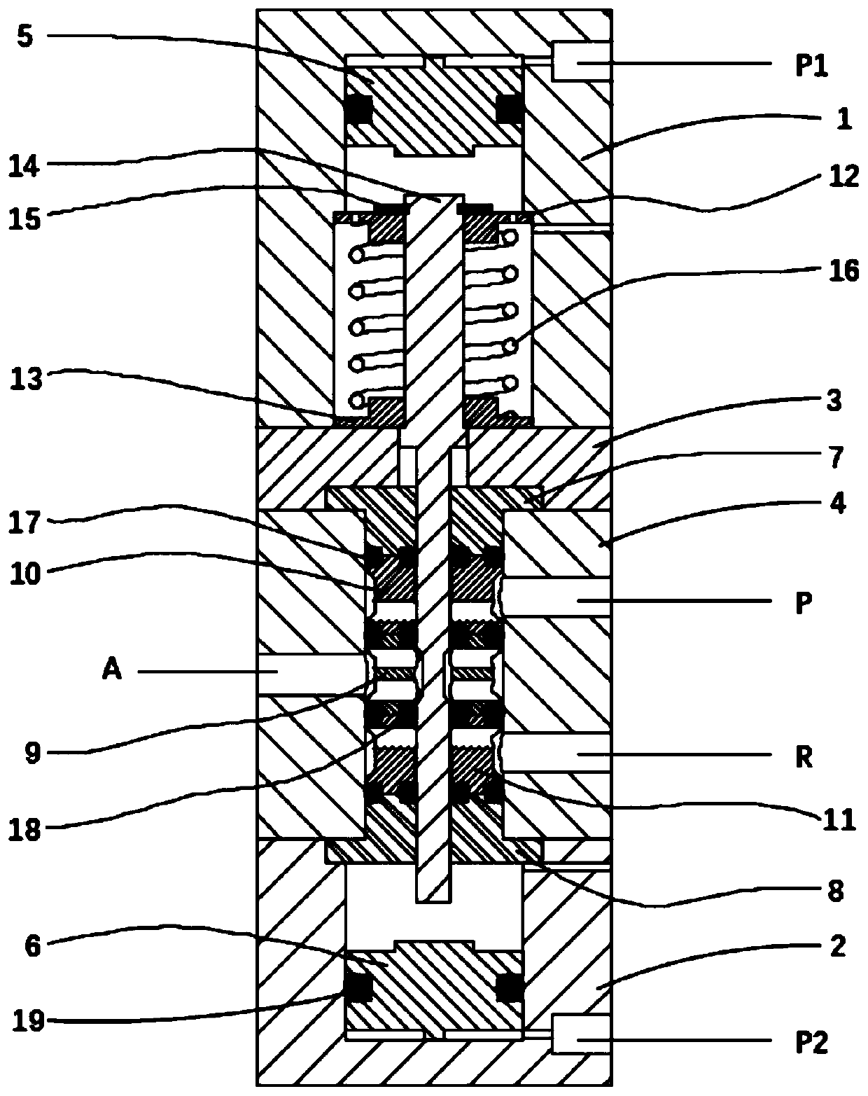
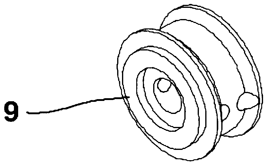
[0021] This embodiment provides a specific structure of a pneumatically controlled three-position three-way reversing valve, such as Figure 1-5 As shown, including valve body 4, it is characterized in that: valve body 4 is provided with upper sealing support 10, middle sealing support 9 and lower sealing support 11 successively along the vertical direction from top to bottom, upper sealing support 10, middle sealing support 9 and the two ends of the lower sealing bracket 11 are respectively provided with a first sealing ring 17 and a second sealing ring 18, and the valve body 4 is provided with an air source port P communicating with the upper sealing bracket 10 and a test port P communicating with the middle sealing bracket 9. Port A and the exhaust port R communicating with the lower seal bracket 11.

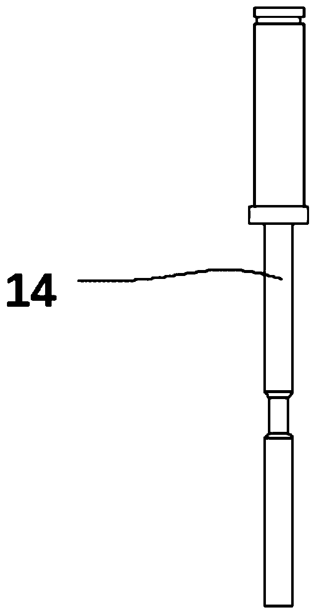
[0022] The two ends of the valve body 4 are respectively provided with an upper guide ring 7 and a lower guide ring 8, and a valve core 14 is interspersed inside the valve bo...


PUM


Abstract

The invention discloses a pneumatic control three-position and three-way reversing valve. The pneumatic control three-position and three-way reversing valve comprises a valve body, an upper sealing bracket, an intermediate sealing bracket and a lower sealing bracket are sequentially arranged in the valve body in the vertical direction from top to bottom, first sealing rings and second sealing rings are correspondingly arranged at the two ends of the upper sealing bracket, the intermediate sealing bracket and the lower sealing bracket, and an air source port communicating with the upper sealingbracket, a testing port communicating with the intermediate sealing bracket, and an exhaust port communicating with the lower sealing bracket are formed in the valve body. The pneumatic control three-position and three-way reversing valve is suitable for the valve body, the gas path switching of pressurization, detection and exhaust of a tested object can be achieved, testing can be conducted bythe negative pressure and the positive pressure, the working pressure range is large, meanwhile the universality of the valve body is high, the structure is compact, the volume is small, and the manufacturing cost of an instrument is effectively lowered.

Description

technical field [0001] The invention belongs to the technical field of valve bodies, in particular to a pneumatically controlled three-position three-way reversing valve. Background technique [0002] The valve body is a major part of the valve, and there are different mechanical manufacturing methods according to the pressure level; [0003] The direct pressure air tightness tester has negative pressure type, positive pressure type, and positive and negative pressure type according to the test pressure type. The working pressure is usually in the range of -100kPa to 2000kPa. The traditional technology usually requires two or more solenoid valves ( Pneumatic control valve) to complete the pressurization, detection, and exhaust gas circuit switching of the test product, such as figure 1 As shown, and according to different test pressures, solenoid valves (pneumatic control valves) of different specifications need to be selected. As a result, the current direct pressure air t...

Claims


Application Information

Patent Timeline
Patent Type & Authority Applications(China)
IPC IPC(8): F16K11/07F16K27/04F16K31/122
CPCF16K11/0712F16K11/0716F16K27/041F16K31/1221F16K31/1225
Inventor 何快生周燕玲
Owner 深圳天邦美科技有限公司
Why Eureka
Try Eureka