
Civil engineering anti-seismic structure

An earthquake-resistant structure and civil engineering technology, applied in the field of earthquake-resistant civil engineering process, can solve the problems of lack of and inability to transport pipes and excellent seismic protection, and achieve the effect of realizing protection and improving protection capability.

Active Publication Date: 2020-08-14
HARBIN UNIV
View PDF6 Cites 6 Cited by
  • Summary
  • Abstract
  • Description
  • Claims
  • Application Information

AI Technical Summary

Problems solved by technology

[0004] However, when we designed the corresponding seismic structure for pipelines, we did not establish a complete and scientific test, so that the designed seismic structure was put into use without sufficient scientific and experimental demonstration, lacking the meaning of perfect and scientific experiments. Therefore, it is impossible to optimize and improve the anti-seismic structure, and then improve its function and improve the anti-seismic protection performance of the pipeline connection parts. As a result, when it is put into production and use in the future, due to the large uncertainty of the magnitude of the earthquake that occurs in different regions, and the It is impossible to produce optimal anti-seismic protection for the pipeline according to the different conditions in different regions;

Method used


Image

  • Civil engineering anti-seismic structure
  • Civil engineering anti-seismic structure
  • Civil engineering anti-seismic structure

Examples


Embodiment 1

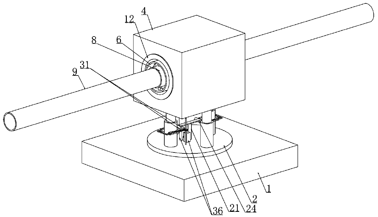
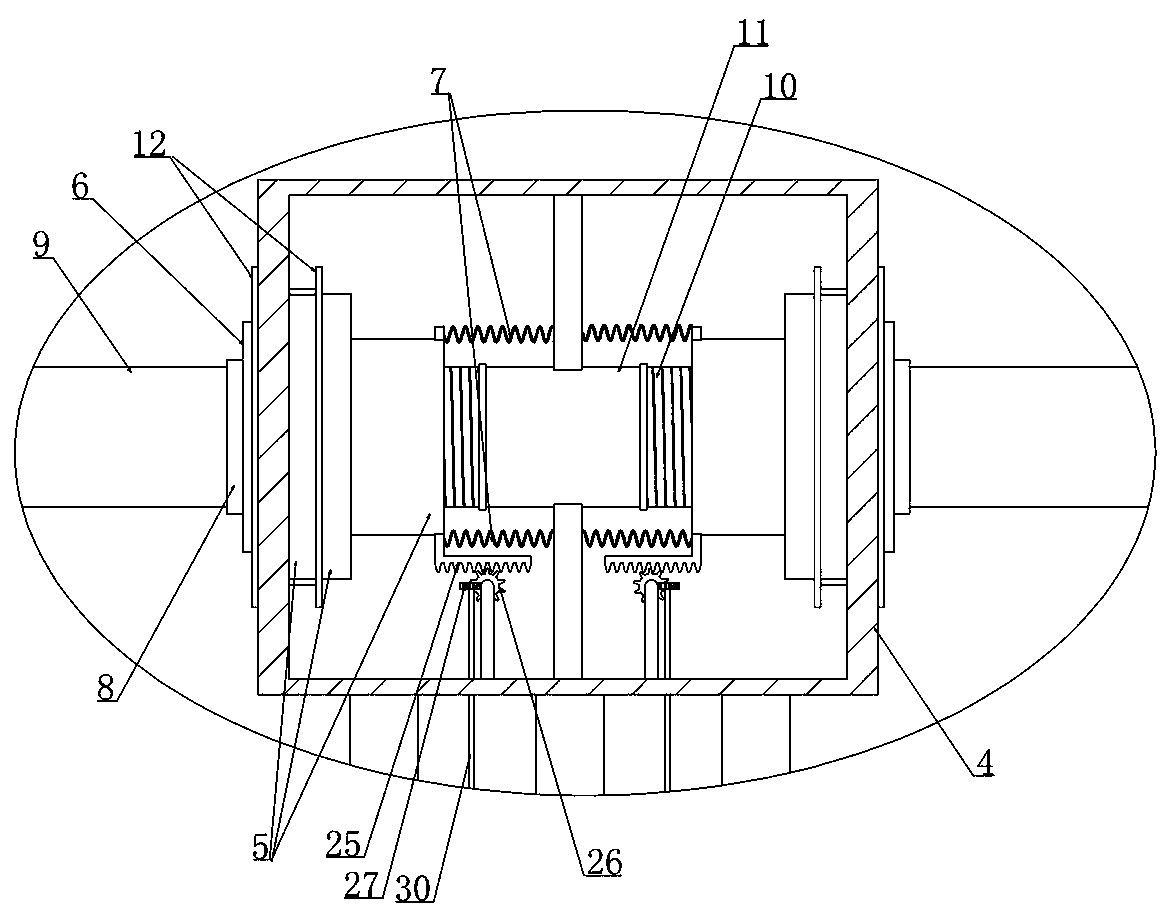
[0044] Embodiment 1, this embodiment provides a kind of civil engineering anti-seismic structure, refer to the attached figure 2 As shown, it includes a base plate 1, which is characterized in that a bearing plate 2 is installed longitudinally slidingly in the base plate 1, and a connection box 4 (the first spring 3 The settings are used to achieve the effect of buffering the connection box 4 when it is subjected to seismic longitudinal waves), refer to the attached image 3 As shown, the horizontal ends of the connection box 4 are respectively horizontally slidable and installed with a moving cylinder 5, referring to the attached Figure 6 As shown, the vertical adjustment ring 6 is installed on both sides of the longitudinal direction of the moving cylinder 5 and the second spring 7 is connected between the moving cylinder 5 and the connecting box 4 (when the moving cylinder 5 moves in the connecting box 4, the second spring is driven 7 stretching, so as to achieve a certa...

Embodiment 2

[0052] Embodiment 2, on the basis of embodiment 1, with reference to appended Figure 9 As shown, the carrier plate 2 is vertically slidably mounted on the bottom wall of the base plate 1 via the cylinder 19 integrally connected with it, and the bottom wall of the base plate 1 is fixedly installed with a slide rail 20 that is longitudinally slidable with the cylinder 19. 19 is coaxially arranged and vertically slidably installed on the locking column 21 of the cylinder 19, and a locking spring 22 is connected between the locking column 21 and the cylinder 19. The sliding rail 20 is provided with a locking hole 23 that matches the locking column 21 ;

[0053]Initially, when the annular baffle plate 12 at one end of the moving cylinder 5 in the connection box 4 does not touch the side wall of the connection box 4, the locking post 21 is inserted into the locking hole provided on the slide rail 20 under the action of the locking spring 22 In 23, the locking effect on the bearing...

Embodiment 3

[0054] Embodiment 3, on the basis of embodiment 1, with reference to appended Figure 7 As shown, the unlocking device includes an L-shaped rack 25 fixedly connected to the moving cylinder 5, and the L-shaped rack 25 is engaged with an unlocking gear 26, and the movement of the moving cylinder 5 synchronously drives the L-shaped rack 25 fixedly connected to it to move. , the L-shaped rack 25 drives the transmission device of the unlocking gear 26 through the unlocking gear 26 meshing with it, referring to the attached Figure 8 As shown, the transmission device of the unlocking gear 26 drives two triangular blocks 28 horizontally slidably mounted on the bearing plate 2 to move toward each other, and the triangular blocks 28 cooperate with the oblique blocks 24 to force the locking column 21 to move upwards, so that the moving cylinder 5. When the annular baffle plate 12 at one end of the connection box 4 touches the side wall of the connection box 4, the locking column 21 is d...


PUM


Abstract

The invention relates to a civil engineering anti-seismic structure. The civil engineering anti-seismic structure effectively solves the problem that an existing civil engineering anti-seismic structure does not subjected to fully scientific demonstration and test demonstration, and then the existing civil engineering anti-seismic structure is put into use, so that the protection effect is causedto be poor. According to the technical solution, the civil engineering anti-seismic structure is characterized in that a retractable hose is arranged between every two adjacent conveying pipes for connection, when an earthquake occurs, a certain displacement can be generated between the every two adjacent conveying pipes in the seismic wave direction, that is, the connecting position of the everytwo conveying pipes can deform to a certain degree, and rigid connection is changed into flexible connection, so that the protection capacity for coping with the earthquake is greatly improved, and the pipeline connecting part is better protected.

Description

technical field [0001] The invention relates to the field of anti-seismic technology of civil engineering process, in particular to an anti-seismic structure of civil engineering. Background technique [0002] The pipe connections in the prior art are mostly realized by clamps. However, the structure in the prior art that realizes the rigid connection of the pipelines through the clamps can realize the sealed connection of two separate pipes, but the joint is subject to external stresses such as earthquakes. Under the action, different degrees of distortion and deformation will occur, or even break, which will affect the sealing between the two separated pipes, resulting in the leakage of transported liquid or gas, etc., which will not only affect the continued use of work, but also cause greater environmental pollution. Problems, unable to meet the use requirements of the anti-seismic function of the pipeline connection; [0003] Therefore, the seismic resistance of pipeli...

Claims


Application Information

Patent Timeline
Patent Type & Authority Applications(China)
IPC IPC(8): F16L27/10F16L3/205G01M7/06
CPCF16L3/205F16L27/10G01M7/06
Inventor 郑熙龙丁宝荣霍健毛春光高红帅张冬久
Owner HARBIN UNIV
Learn More