Method for detecting relative angle of small circular hole of revolving body thin-walled part

A thin-walled parts, relative angle technology, applied in the field of parts inspection, can solve the problems of small angle, slow process, large error and so on

Active Publication Date: 2020-08-14
CHINA FIRST AUTOMOBILE
View PDF7 Cites 5 Cited by
  • Summary
  • Abstract
  • Description
  • Claims
  • Application Information

AI Technical Summary

Problems solved by technology

[0004] When measuring the small round hole processed on the thin wall of the thin-walled rotary part according to the existing technology, the thin-walled rotary part, usually a shaft part, is basically characterized by the axis as the reference, and there is no characteristic element for establishing a coordinate system. The angle between adjacent small holes processed on the radial circumference is small and the tolerance requirements are relatively strict. If these small holes are measured in the form of a cylinder, the fi

Method used


Image

  • Method for detecting relative angle of small circular hole of revolving body thin-walled part
  • Method for detecting relative angle of small circular hole of revolving body thin-walled part
  • Method for detecting relative angle of small circular hole of revolving body thin-walled part

Examples


Embodiment 1

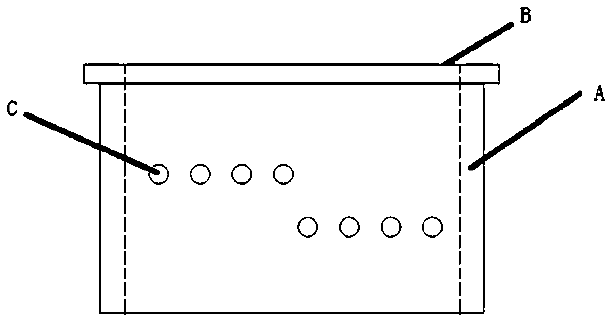
[0046] like figure 2 As shown, the clutch bushing is taken as an example, the wall thickness is 3mm, and the outer ring of the bushing is divided into upper and lower layers in the radial direction, and a total of 8 small holes with a diameter of D4mm are processed. The angle between adjacent holes is small and the tolerance requirements are strict.

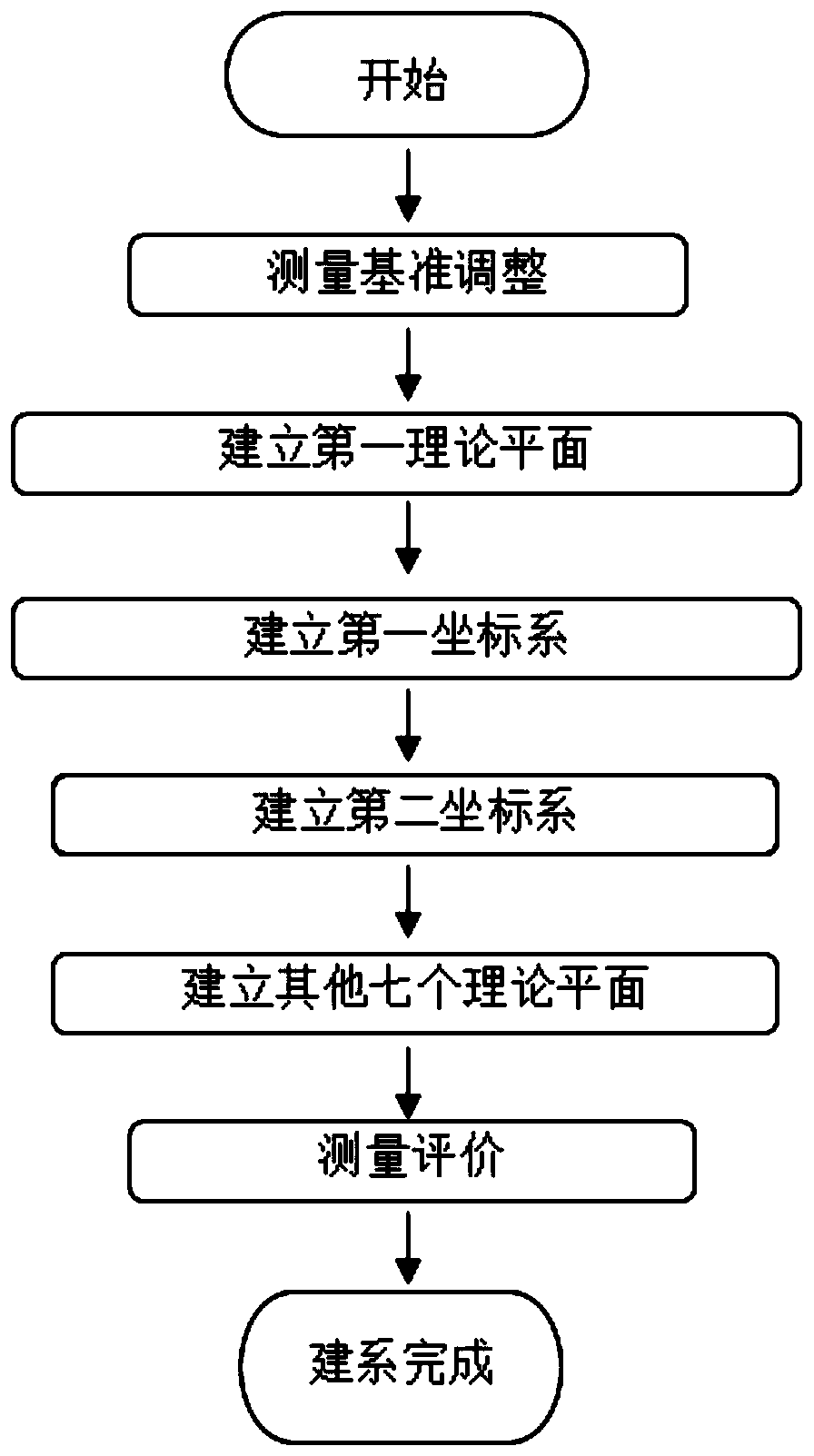
[0047] A method for detecting the relative angle of a small circular hole in a thin-walled part of a rotating body, comprising the following steps:

[0048] The first step is to adjust the measurement benchmark:

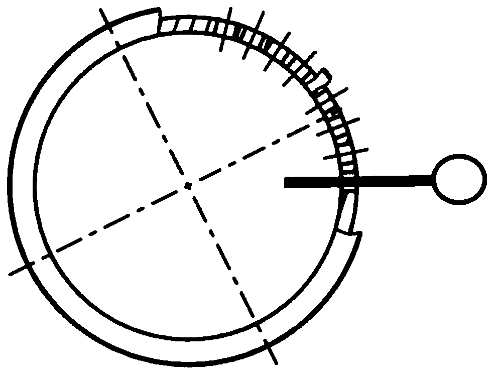
[0049] The thin-walled parts of the rotating body are placed on the measuring table so that the axis of rotation of the thin-walled parts of the rotating body, that is, the central axis of the reference cylinder A, is placed perpendicular to the XY plane of the measuring table. First, make the measuring rod and the X-axis direction of the measuring equipment consistent, such as figure 2 , image 3 As shown, adjust th...


PUM


Abstract

The invention discloses a method for detecting the relative angle of a small circular hole of a revolving body thin-walled part. The method comprises the steps of adjusting the measurement reference,specifically, enabling the revolving body thin-walled part to be vertically placed on a measurement platform, enabling a measurement rod to extend into a measured small hole and be concentric with themeasured small hole, and enabling the normal direction of the measured small hole to be consistent with the X axis of measurement equipment; establishing a first theoretical plane, specifically, establishing a vertical reference plane of the small hole C by taking the central axial direction of a reference cylinder A as a reference direction; establishing a first coordinate system, specifically,taking the small hole C as a space circle for measurement, taking a top surface B of the revolving body part as a first axial Z-direction constraint plane, jointly projecting circle center points of the space circles extracted by the reference cylinder A and the small hole C onto the first axial Z-direction constraint plane, connecting the circle center of the projection of the reference cylinderA with the circle center point of the small hole C, and performing second axial constraint; establishing a second coordinate system, specifically, performing coordinate system rotation according to aninitial angle marked by the drawing to obtain the second coordinate system; establishing other theoretical planes; and conducting measurement evaluation.

Description

technical field [0001] The invention belongs to the technical field of parts detection, and in particular relates to a method for detecting the relative angle of a small circular hole of a thin-walled part of a revolving body. Background technique [0002] Thin-walled rotary parts, usually shaft parts, are characterized by the axis as the reference, and there are no characteristic elements for conventionally establishing a coordinate system. The diameter of the round hole processed on the thin-walled circumference is usually relatively small, such as the attached figure 2 The shown clutch oil-guiding bush has a wall thickness of 3mm. The circumference is divided into upper and lower layers and a total of 8 small holes with a diameter of 4mm are machined. They are oil-guiding holes. The angle between adjacent holes is small and the tolerance requirements are strict. Taking this part as an example, a wall thickness of 3mm means that a hole with a diameter of 4mm can measure a ...

Claims


Application Information

Patent Timeline
IPC IPC(8): G01B21/24
CPCG01B21/24
Inventor 何艳玲祝小超邸太龙李倩王彬彬李国通尚谦
Owner CHINA FIRST AUTOMOBILE
Why Eureka
Try Eureka