Method of calibrating engine blade measuring apparatus

A technology of engine blades and measuring devices, which is applied in the direction of measuring devices, instruments, etc., can solve the problems that cannot truly reflect the accuracy of blades, and achieve the effect of improving consistency and measurement accuracy

Inactive Publication Date: 2017-03-15
CHINA PRECISION ENG INST FOR AIRCRAFT IND AVIC
View PDF11 Cites 3 Cited by
  • Summary
  • Abstract
  • Description
  • Claims
  • Application Information

AI Technical Summary

Problems solved by technology

[0003] In view of the fact that the measurement and evaluation method of the measurement system in the field of aeroengine blade measurement cannot truly reflect the accuracy of the blade, the present invention proposes a method for calibrating the blade measurement device based on the calibration device, and performs specific position space calibration of the blade measurement device. Error compensation to improve engine blade measurement accuracy

Method used


Image

  • Method of calibrating engine blade measuring apparatus
  • Method of calibrating engine blade measuring apparatus

Examples


Embodiment Construction

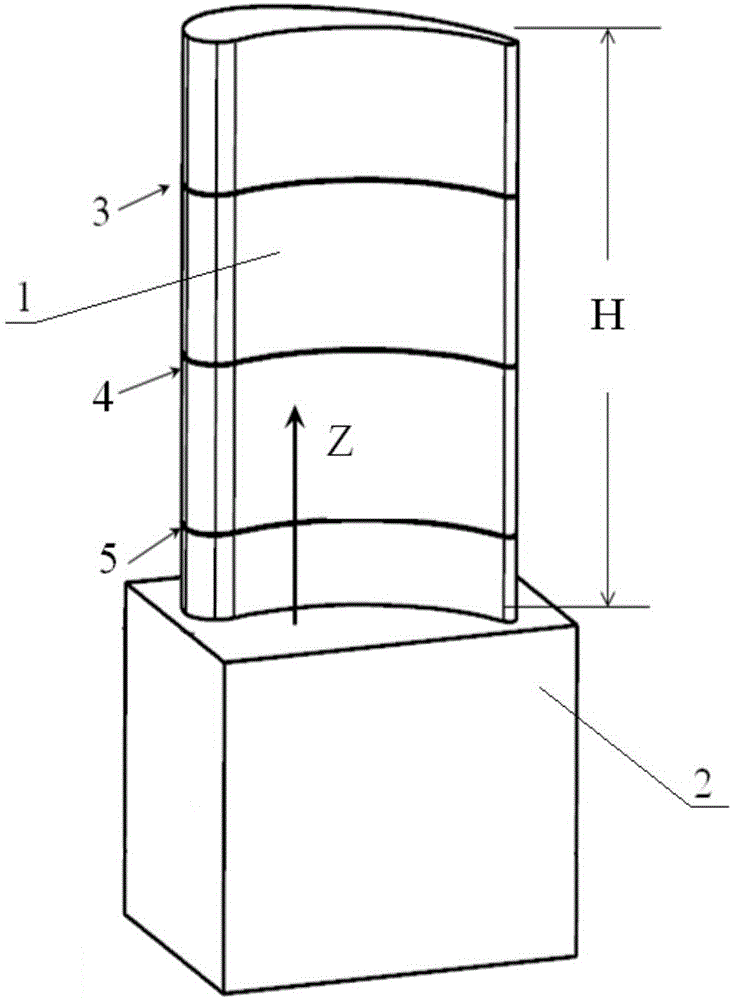
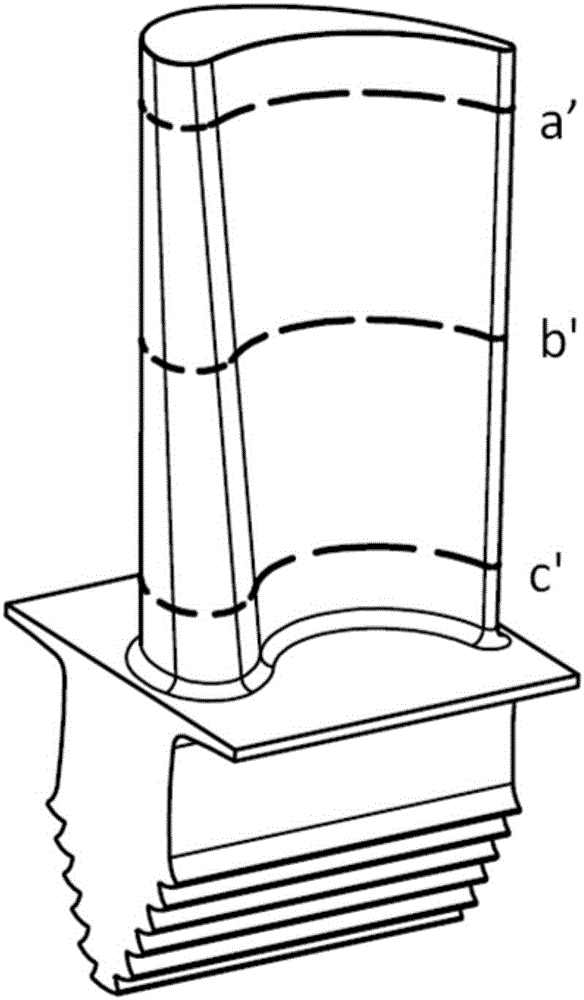
[0016] A method for calibrating an engine blade measuring device, the method uses a special calibration device, the calibration device includes a blade airfoil 1 and a blade tenon root 2, wherein the airfoil 1 is formed by a standard cross-section extending in the normal direction, the standard The cross section is composed of the cross section of the three-dimensional model of the theoretical engine blade at any position in the direction of the stacking axis; when calibrating, first, place the calibration device at the standard measurement position of the measuring device to establish a workpiece coordinate system; then, based on the calibration For the three-dimensional digital model of the device, set three measurement positions 3, 4, and 5 within the range of the height H of the calibration device and measure the cross-sectional parameters of the corresponding positions, and obtain the air intake edge of the calibration device at each measurement position through statistical...


PUM


Abstract

The invention belongs to the test field of aeroengine blade measurement and relates to a method of calibrating a measuring apparatus using a standard molded surface blade. In an engine blade measurement test, the obtained measurement evaluation result by means of measuring a high-precision engine blade cannot truly reflect the precision of the engine blade totally because of the error of the blade evaluation method and the mechanical error of a measuring apparatus. The invention provides a measuring apparatus calibrating method based on a calibration standard molded surface of a blade measuring apparatus. The measuring apparatus calibrating method based on a calibration standard molded surface of a blade measuring apparatus utilizes a special calibrating apparatus. The calibrating apparatus includes a blade body and a blade tenon root, wherein the blade body is formed through normal extension of a standard cross section; the standard cross section is formed by the cross section, at any position of a stacking shaft, of a theoretical engine blade three dimensional model; an error compensation database for each parameter of the measuring apparatus is established; and error compensation for the special position space is performed on the blade measuring apparatus so as to improve the measuring precision of the engine blade.

Description

technical field [0001] The invention belongs to the field of measurement and testing of aeroengine blades, and relates to a method for calibrating an engine blade measurement device. Background technique [0002] At present, the measurement accuracy and poor consistency of key parameters of aero-engine blades have been plagued by aviation personnel in our country. In the engine blade measurement test, the measurement and evaluation results obtained by measuring high-precision engine blades cannot truly reflect the accuracy of the engine blades at all. This is caused by the error of the blade evaluation method of the measuring device and the mechanical error, and the mechanical accuracy of the current measuring equipment can better meet the high-precision measurement requirements. Therefore, the main cause of poor blade measurement accuracy and consistency is the error of the blade evaluation method of the measurement device. Not only that, the efficiency of blade detection...

Claims


Application Information

Patent Timeline
Patent Type & Authority Applications(China)
IPC IPC(8): G01B21/04
CPCG01B21/045
Inventor 郑会龙刘京亮刘飞庞春超张斌马艺航
Owner CHINA PRECISION ENG INST FOR AIRCRAFT IND AVIC
Why Eureka
Try Eureka