Check patentability & draft patents in minutes with Patsnap Eureka AI!

Portable environmental monitoring device for mine geology

A technology for environmental monitoring and monitoring devices, applied in the direction of measuring devices, measuring instrument components, instruments, etc., can solve problems such as the inability of monitoring devices to be placed stably

Inactive Publication Date: 2020-08-14
宁波精致诚检测技术服务有限公司
View PDF0 Cites 1 Cited by
  • Summary
  • Abstract
  • Description
  • Claims
  • Application Information

AI Technical Summary

Problems solved by technology

[0003] The purpose of the invention is to solve the shortcomings in the prior art that the monitoring device cannot be placed stably, and propose a portable environmental monitoring device for mine geology

Method used


Image

  • Portable environmental monitoring device for mine geology
  • Portable environmental monitoring device for mine geology
  • Portable environmental monitoring device for mine geology

Examples


Embodiment 1

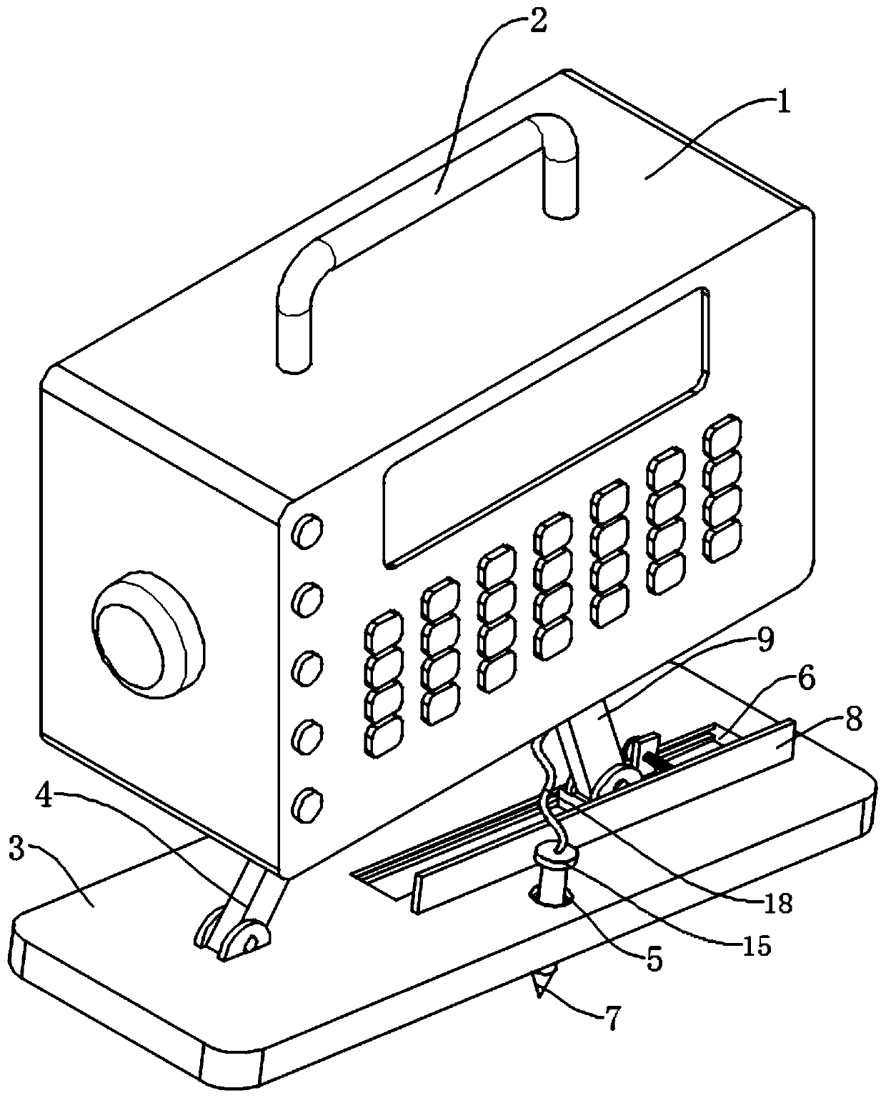
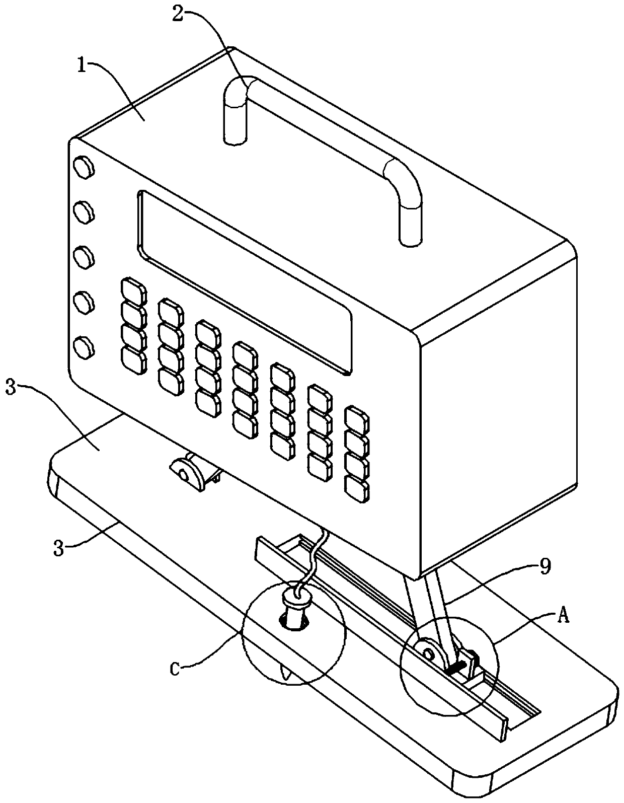
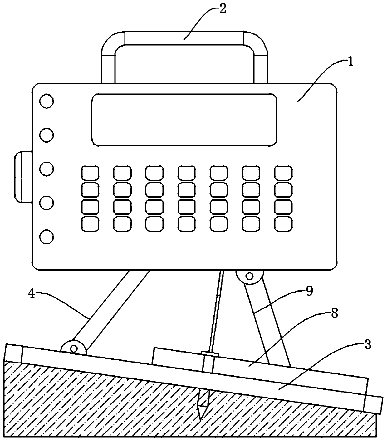
[0024] refer to Figure 1-8 , a device for portable environmental monitoring of mine geology, including a monitoring device body 1, a handle 2 is fixedly connected to the middle of the upper end of the monitoring device body 1, and the handle 2 is designed to carry the device.

[0025] A support plate 4 is fixedly connected to the lower end of the monitoring device body 1, and a bottom plate 3 is hinged to the lower end of the support plate 4. The bottom plate 3 is provided with a chute 6, and a slider 10 is slidably arranged in the chute 6. The slider 10 and the chute 6 are connected by a limit mechanism, the limit mechanism includes limit grooves 19 opened on the inner walls of both sides of the chute 6, both sides of the slider 10 are fixedly connected with limit blocks 20, and the limit blocks 20 are slidably arranged at In the limit slot 19, by adjusting the position of the slider 10 in the chute 6, the inclination angle of the hinge plate 9 is adjusted so as to drive the...

Embodiment 2

[0028] refer to figure 1 , figure 2 , Figure 7 , as another preferred embodiment of the invention, the difference from Embodiment 1 is that the middle position of the bottom plate 3 is provided with a fixing hole 5, the lower bottom wall of the fixing hole 5 is provided with a communication hole 17, and the inner diameter of the communication hole 17 is smaller than the fixed hole 17. The inner diameter of the hole 5, the communication hole 17 is inserted with a fixed column 7, the lower end of the fixed column 7 is fixedly connected with a pointed tip 16, the upper end of the fixed column 7 is fixedly connected with a connecting cap 15, and the fixed column 7 and the pointed tip 16 are made of stainless steel At the same time, it is made of stainless steel, which is beneficial to prevent the fixing column 7 and the tip 16 from being damp and rotten, and the volume of the connecting cap 15 matches the volume of the fixing hole 5. By inserting the fixing column 7 into the gr...

Embodiment 3

[0030] refer to Figure 1-4 , as another preferred embodiment of the invention, the difference from Embodiment 2 is that the upper end of the connecting cap 15 is connected with a connecting rope 18, and the connecting rope 18 is connected with the monitoring device body 1. Through the design of the connecting rope 18, When the fixed column 7 is pulled out of the ground, it plays a role of suspension, which is beneficial to prevent the fixed column 7 from being lost when it is pulled out.


PUM


Abstract

The invention relates to the technical field of environment monitoring, and especially relates to a portable environment monitoring device for mine geology. The device comprises a monitoring device body, a handle is fixedly connected to the middle of the upper end of the monitoring device body, one side of the lower end of the monitoring device body is fixedly connected with a supporting plate, abottom plate is hinged to the lower end of the supporting plate, a sliding groove is formed in the bottom plate, a sliding block is arranged in the sliding groove in a sliding mode, the sliding blockand the sliding groove are connected through a limiting mechanism, a hinge plate is hinged to the sliding block, the upper end of the hinge plate is hinged to the monitoring device body, a connectingplate is fixedly connected to the sliding block, a threaded rod is connected to the connecting plate in a threaded penetrating mode, and a fixing plate fixedly connected with the bottom plate is arranged on one side of the sliding groove. The stability of the device during placement is facilitated, and it is guaranteed that the device is always parallel to the horizontal direction.

Description

technical field [0001] The invention relates to the technical field of environmental monitoring, in particular to a portable environmental monitoring device for mine geology. Background technique [0002] Environmental monitoring refers to the determination of environmental quality (or pollution degree) and its changing trend by measuring the representative values ​​of factors affecting environmental quality. The main means of environmental monitoring include physical means, chemical means and biological means. In the environmental monitoring of mine geology, environmental monitoring is used for monitoring. However, due to the inclination of the mine, the bottom of the existing monitoring device is horizontal. When the device is monitored, it is easy to cause the device to be unstable. , it is difficult to keep the monitoring level, which is not conducive to the monitoring. SUMMARY OF THE INVENTION [0003] The purpose of the invention is to solve the disadvantage that t...

Claims


Application Information

Patent Timeline
Patent Type & Authority Applications(China)
IPC IPC(8): G01D11/00G01D11/30
CPCG01D11/00G01D11/30
Inventor 郑肖邓立林蒋辉刘亚强
Owner 宁波精致诚检测技术服务有限公司
Features
  • R&D
  • Intellectual Property
  • Life Sciences
  • Materials
  • Tech Scout
  • Unparalleled Data Quality
  • Higher Quality Content
  • 60% Fewer Hallucinations
Learn More