Eureka AIR delivers breakthrough ideas for toughest innovation challenges, trusted by R&D personnel around the world.

Driving control circuit, method and device and air conditioner

A technology for driving control circuits and driving circuits, which is applied in the direction of circuit devices, emergency protection circuit devices, emergency protection devices with automatic disconnection, etc., and can solve the problem of low reliability of containers, failure to meet reliability requirements, and low reliability of container protection schemes and other issues to achieve the effect of improving reliability

Inactive Publication Date: 2020-08-14
GD MIDEA HEATING & VENTILATING EQUIP CO LTD +1
View PDF4 Cites 0 Cited by
  • Summary
  • Abstract
  • Description
  • Claims
  • Application Information

AI Technical Summary

Problems solved by technology

[0002] In the related technical solutions, the container protection scheme usually adopts a single electronic control scheme to realize the container protection. Taking the pressure vessel protection scheme as an example, under normal circumstances, it is necessary to install a pressure relief valve controlled by a drive circuit on the pressure pipeline of the pressure vessel. When the pressure is too high, the pressure relief valve will act to release the pipeline pressure, but the control process of the pressure relief valve will involve the action of the circuit connected to the drive circuit, and the circuit connected to the drive circuit will There will be actions of electronic devices such as semiconductors and / or relays. Since electronic devices such as semiconductors and / or relays are unreliable devices, the reliability of existing container protection schemes is low and cannot meet the current reliability requirements. Causes pressure relief valves to fail to release pressure accurately, resulting in less reliable container operation

Method used


Image

  • Driving control circuit, method and device and air conditioner
  • Driving control circuit, method and device and air conditioner
  • Driving control circuit, method and device and air conditioner

Examples


Embodiment 1

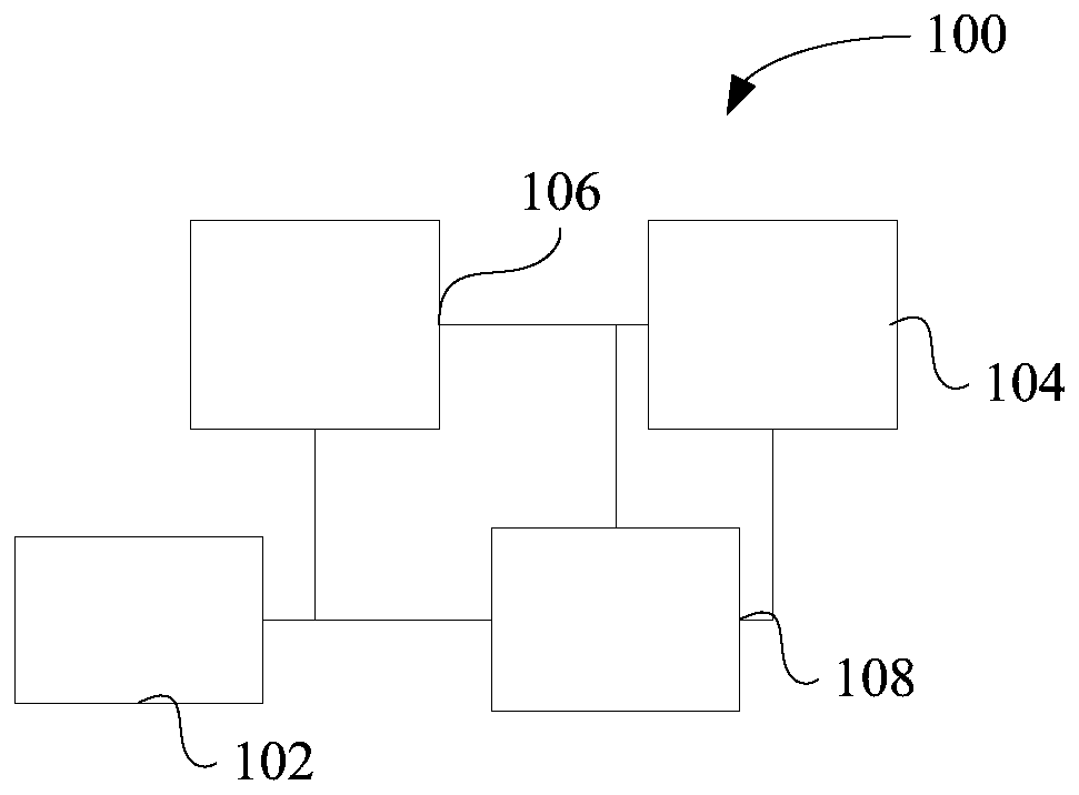
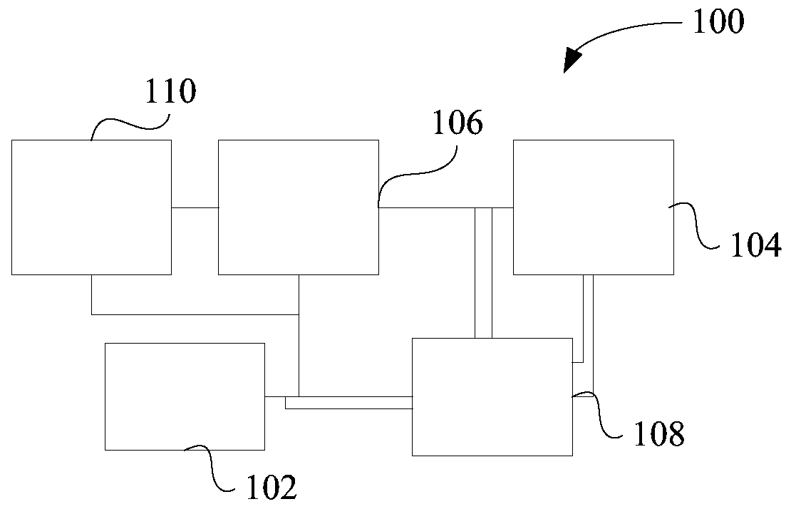
[0063] In one embodiment of the present invention, as figure 1 , figure 2 and image 3 As shown, a drive control circuit 100 is provided, wherein the drive control circuit 100 includes: a drive circuit 104 , a detection device 102 , a protection circuit 106 and a first controller 108 . Specifically, the detection device 102 is configured to output an action signal according to the received working condition parameters; the input end of the protection circuit 106 is connected to the detection device 102, the output end of the protection circuit 106 is connected to the input end of the drive circuit 104, and the protection circuit 106 is configured to receive the action signal and stop outputting the driving signal to the driving circuit 104; the input end of the first controller 108 is connected with the output end of the detection device 102 and the protection circuit 106, and the output end of the first controller 108 is connected with the driving circuit 106. The circuit ...

Embodiment 2

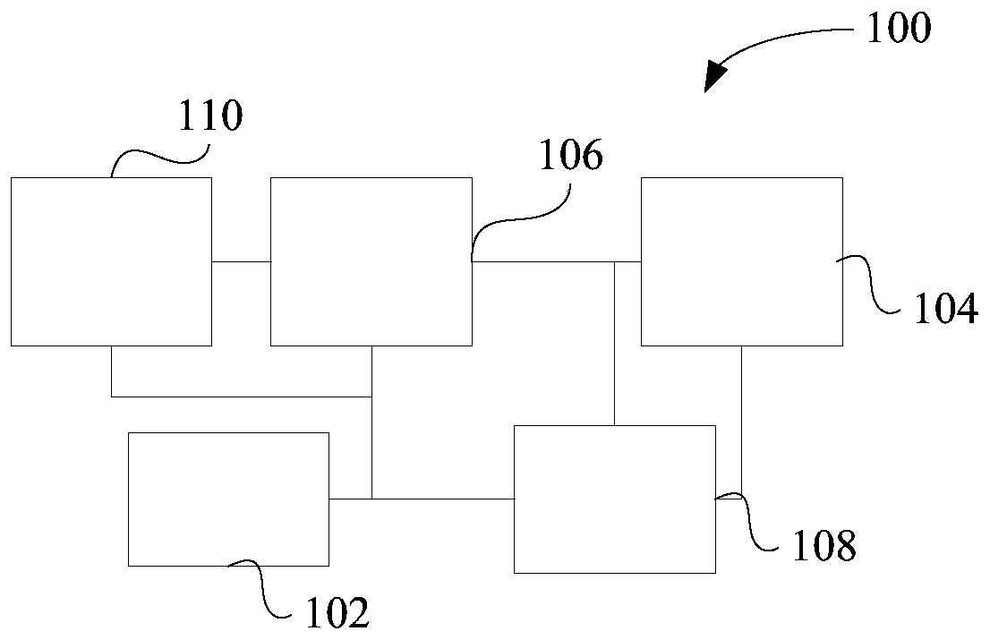
[0072] In one embodiment of the present invention, a drive control circuit 100 is provided, such as figure 2 As shown, the drive control circuit 100 includes: a drive circuit 104 , a detection device 102 , a protection circuit 106 , a first controller 108 and a second controller 110 . Specifically, the detection device 102 is configured to output an action signal according to the received working condition parameters; the input end of the protection circuit 106 is connected to the detection device 102, the output end of the protection circuit 106 is connected to the input end of the drive circuit 104, and the protection circuit 106 is configured to receive the action signal and stop outputting the driving signal to the driving circuit 104; the input end of the first controller 108 is connected with the output end of the detection device 102 and the protection circuit 106, and the output end of the first controller 108 is connected with the driving circuit 106. The circuit 104...

Embodiment 3

[0075] In any of the above embodiments, if figure 1 , figure 2 and image 3 As shown, the first controller 108 is further configured to: determine that the driving circuit 104 stops working, and output a first warning message.

[0076] In this embodiment, when it is determined that the drive control circuit 100 stops running, a first warning message is issued, so that maintenance personnel can maintain the faulty protection circuit 106 in time, thereby improving the reliability of the drive control circuit 100 .

[0077] In any of the above embodiments, the first controller 108 is further configured to: run a self-test program, determine that the self-test result indicated by the self-test program does not satisfy a preset test result, and control the driving circuit 104 to stop working.

[0078] In this embodiment, the first controller 108 executes the self-test program and compares the self-test result indicated by the self-test program with the preset test result, so tha...


PUM


Abstract

The invention provides a driving control circuit, a driving control method, a driving control device and an air conditioner. The driving control circuit comprises: a driving circuit; a detection device, wherein the detection device is configured to output an action signal according to the received working condition parameters; a protection circuit, wherein the input end of the protection circuit is connected with the detection device, the output end of the protection circuit is connected with the input end of the driving circuit, and the protection circuit is configured to receive the action signal and stop outputting the driving signal to the driving circuit; and a first controller, wherein the input end of the first controller is connected with the output ends of the detection device andthe protection circuit, the output end of the first controller is connected with the driving circuit, and the first controller is configured to receive the action signal and / or at least part of the driving signal and control the driving circuit to stop working. In the technical scheme, the influence of unreliable connection of the protection circuit and each circuit on the reliability of the driving control circuit during operation is reduced.

Description

technical field [0001] The present invention relates to the technical field of drive control, in particular to a drive control circuit, method, device and air conditioner. Background technique [0002] In the related technical solutions, the container protection scheme usually adopts a single electronic control scheme to realize the container protection. Taking the pressure vessel protection scheme as an example, under normal circumstances, it is necessary to install a pressure relief valve controlled by a drive circuit on the pressure pipeline of the pressure vessel. When the pressure is too high, the pressure relief valve will act to release the pipeline pressure, but the control process of the pressure relief valve will involve the action of the circuit connected to the drive circuit, and the circuit connected to the drive circuit will There will be actions of electronic devices such as semiconductors and / or relays. Since electronic devices such as semiconductors and / or r...

Claims


Application Information

Patent Timeline
IPC IPC(8): H02H5/00F24F11/89F24F11/88F24F11/64F24F11/32H02H3/05
CPCH02H5/00F24F11/89F24F11/88F24F11/64F24F11/32H02H3/05
Inventor 赵海龙洪伟鸿刘凯
Owner GD MIDEA HEATING & VENTILATING EQUIP CO LTD
Why Eureka
Eureka Blog
Learn More