Monitoring cabinet, monitoring system and monitoring method based on cabinet space occupation detection

A monitoring system and cabinet technology, which is applied in the direction of cabinet/box/drawer parts, geophysical measurement, electrical equipment housing/cabinet/drawer, etc., can solve the problems of cumbersome management, high cost, limited service life of batteries, etc. , to achieve the effect of convenient management and operation, simple structure and improved accuracy

Pending Publication Date: 2020-08-14
SHENZHEN EPLU SCI TECH
View PDF12 Cites 0 Cited by
  • Summary
  • Abstract
  • Description
  • Claims
  • Application Information

AI Technical Summary

Problems solved by technology

[0003] In the existing technology, asset management and U-position occupancy are generally managed through asset tags, infrared monitoring, or NFC technology, but these management technologies or methods are insufficient, for example, the cost of using asset tags is relatively high , the management is cumbersome and human operation is prone to omissions; infrared monitoring needs to paste source infrared tags on the server and U position, the cost is high and the service life is limited by the battery; NFC (Near Field Communication, near field communication) / RFID (Radio Frequency Identification, Radio frequency identification) technology cannot accurately detect the U position, and cannot detect devices that occupy multiple U positions

Method used


Image

  • Monitoring cabinet, monitoring system and monitoring method based on cabinet space occupation detection
  • Monitoring cabinet, monitoring system and monitoring method based on cabinet space occupation detection
  • Monitoring cabinet, monitoring system and monitoring method based on cabinet space occupation detection

Examples


Embodiment Construction

[0034] In order to make the object, technical solution and advantages of the present invention clearer, the present invention will be further described in detail below in conjunction with the accompanying drawings and embodiments. It should be understood that the specific embodiments described here are only used to explain the present invention, not to limit the present invention.

[0035] It should be noted that the terms "setting" and "connecting" should be understood in a broad sense, for example, they can be directly set and connected, or indirectly set and connected through a central component or a central structure.

[0036] In addition, if there are "longitudinal", "transverse", "length", "width", "thickness", "upper", "lower", "front", "rear", "left", " Terms such as "right", "vertical", "horizontal", "top", "bottom", "inner", "outer", etc. indicate the orientation or positional relationship, which are based on the orientation or positional relationship shown in the dr...


PUM


Abstract

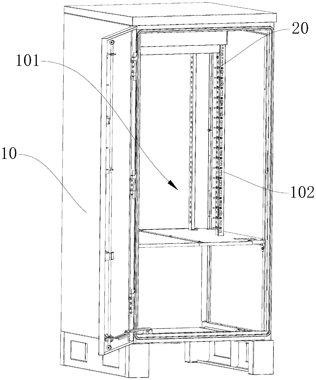
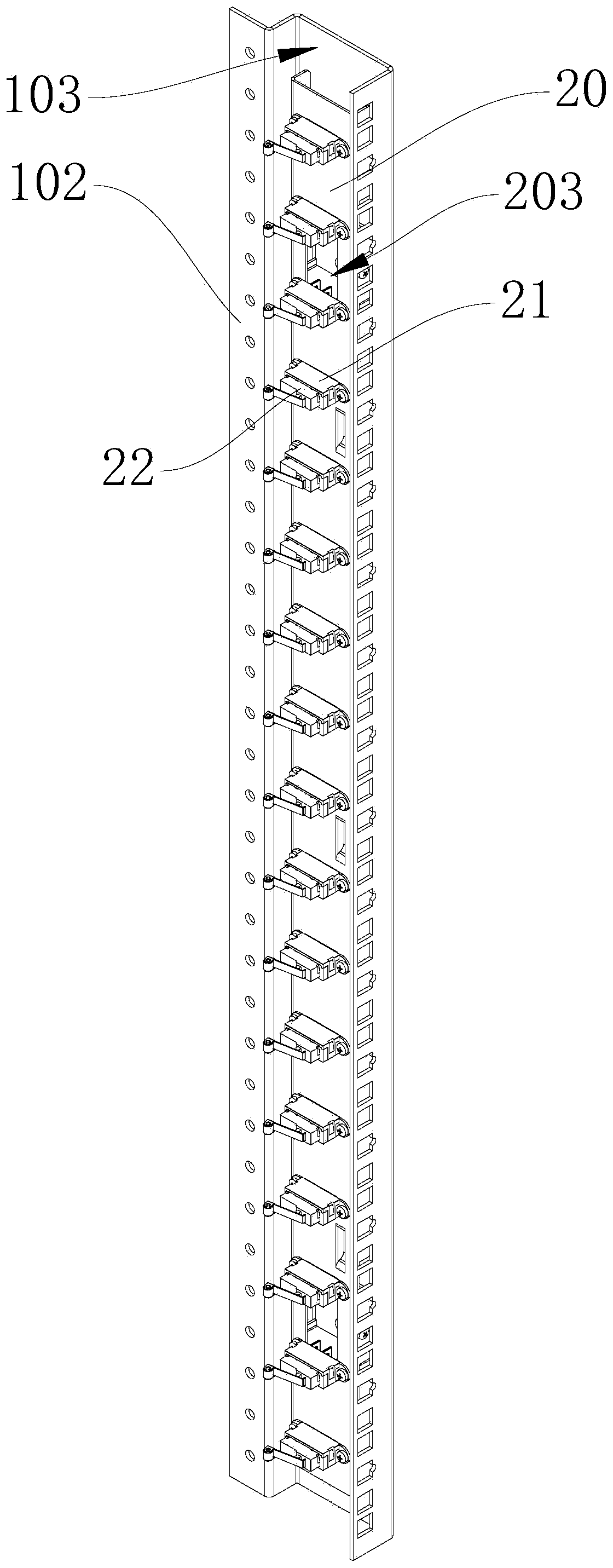
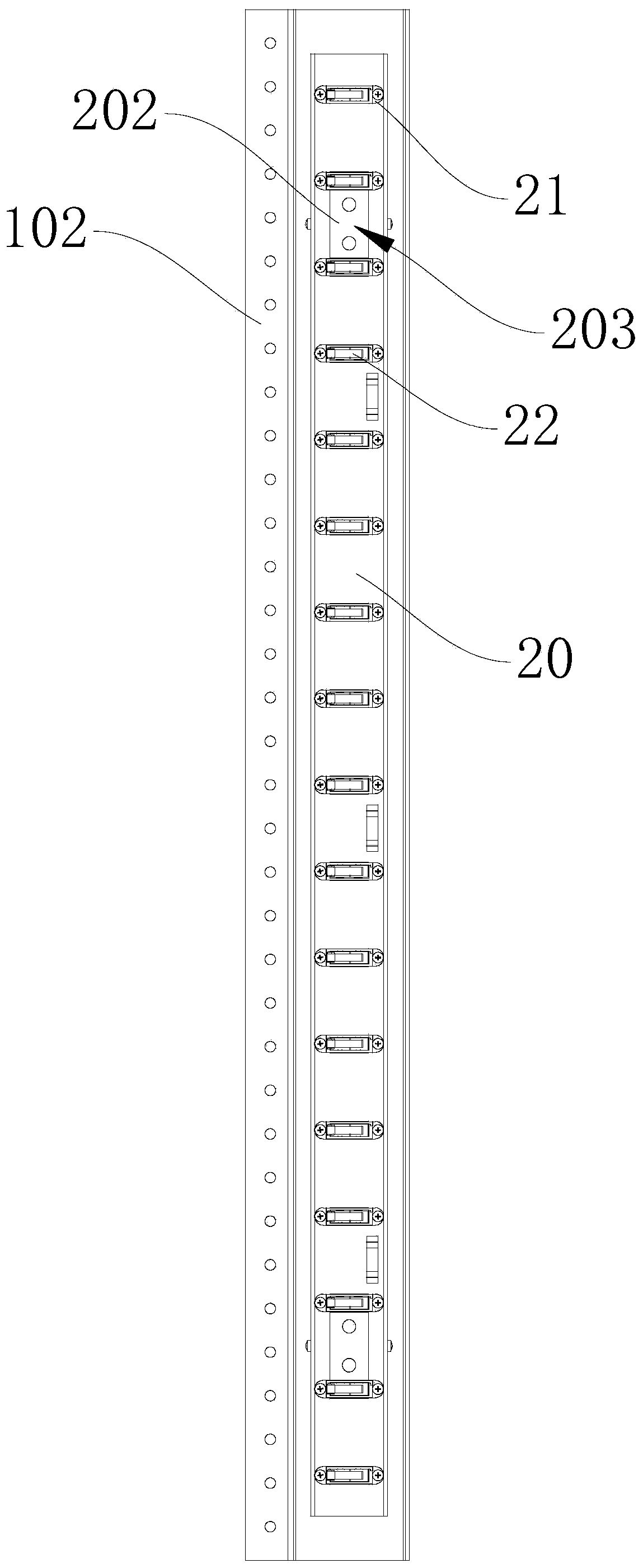
The invention is suitable for cabinet equipment. The invention discloses a monitoring cabinet, a monitoring system and a monitoring method based on cabinet space occupation detection. The monitoring cabinet comprises a cabinet body provided with a plurality of equipment installation positions, the monitoring cabinet further comprises an installation support arranged in the cabinet body, a detection piece capable of being triggered by equipment installed at the equipment installation positions, and a detection module connected with the detection piece, the mounting bracket is provided with a plurality of connecting structures capable of adjusting mounting positions at intervals, and the detection piece is detachably connected to the mounting bracket through the connecting structures. According to the monitoring cabinet, the monitoring system and the monitoring method based on cabinet space occupation detection provided by the invention, the monitoring cabinet is simple in structure, convenient to manage and operate and relatively low in cost, and meanwhile, the U-position occupation condition can be accurately detected.

Description

technical field [0001] The invention belongs to the field of cabinet equipment, and in particular relates to a monitoring cabinet, a monitoring system and a monitoring method based on cabinet space occupancy detection. Background technique [0002] In today's digital and information age, a large amount of information is transmitted through the network, and the data center has become an important part of information transmission. In order to facilitate management, network equipment such as servers and network communication equipment in the data center need to be stored in the cabinet, and the background management personnel need to monitor and manage the occupancy of the U position (that is, the equipment installation position) of the cabinet and the assets such as servers stored in the cabinet . [0003] In the existing technology, asset management and U-position occupancy are generally managed through asset tags, infrared monitoring, or NFC technology, but these management...

Claims


Application Information

Patent Timeline
Patent Type & Authority Applications(China)
IPC IPC(8): H05K5/02G01V9/00
CPCH05K5/0234H05K5/0247H05K5/0217G01V9/00
Inventor 黄顺堂王志彬张国斌
Owner SHENZHEN EPLU SCI TECH
Why Eureka
Try Eureka