
Slaughtering equipment for animal husbandry

A kind of equipment and box technology, applied in the direction of slaughtering, livestock slaughtering table/slaughtering support, slaughtering device, etc., can solve the problems of low efficiency, animal fixation, and difficult slaughtering process, and achieve great application prospects, simple and reasonable structure, Improving the effect of fixed effects

Inactive Publication Date: 2020-08-18
沈飞红
View PDF0 Cites 2 Cited by
  • Summary
  • Abstract
  • Description
  • Claims
  • Application Information

AI Technical Summary

Problems solved by technology

[0003] For now, in the existing animal husbandry, it is usually difficult to effectively fix the animals when slaughtering larger animals, resulting in difficulties in the slaughtering process, and most of them are slaughtered manually, which is inefficient; and then proposes a Slaughtering equipment for livestock

Method used


Image

  • Slaughtering equipment for animal husbandry
  • Slaughtering equipment for animal husbandry
  • Slaughtering equipment for animal husbandry

Examples


Embodiment 1

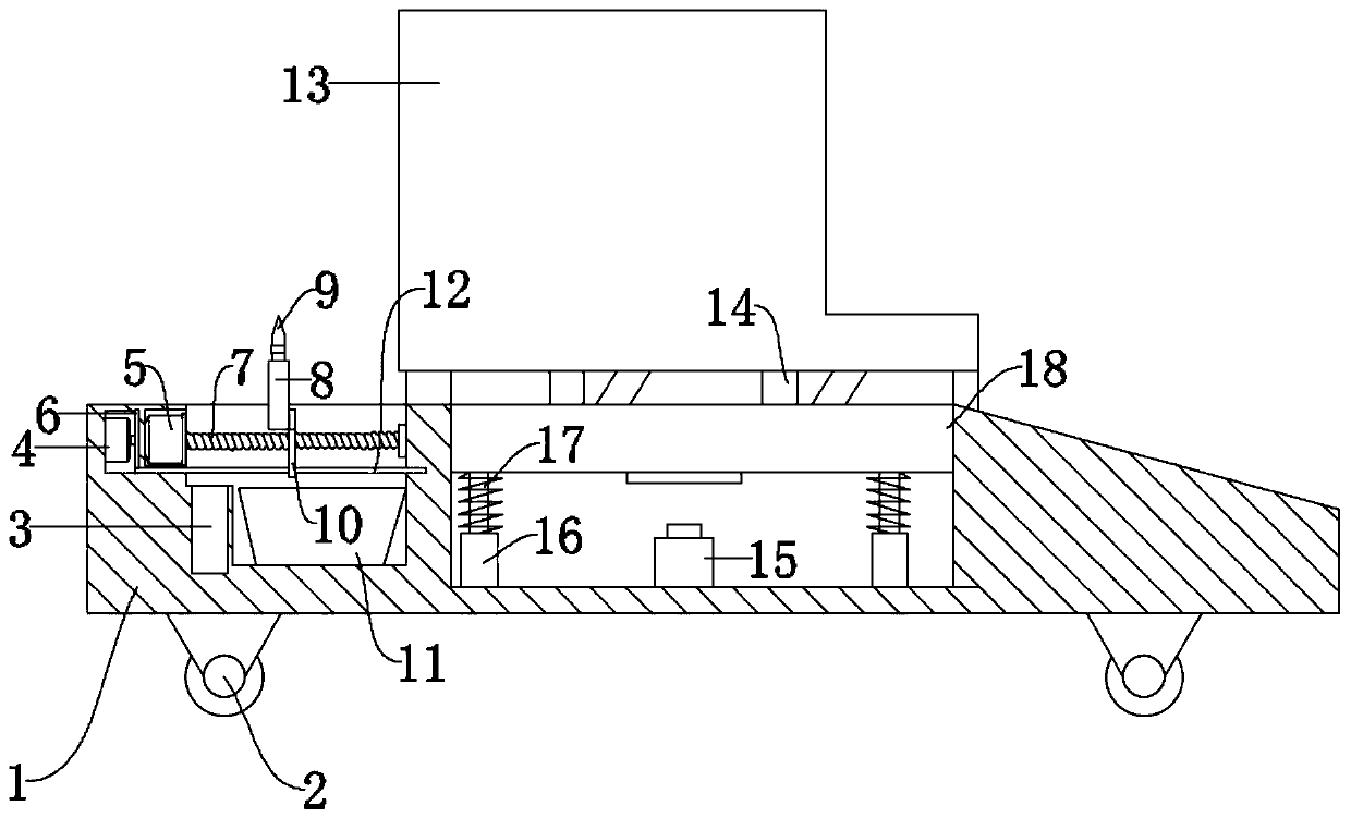
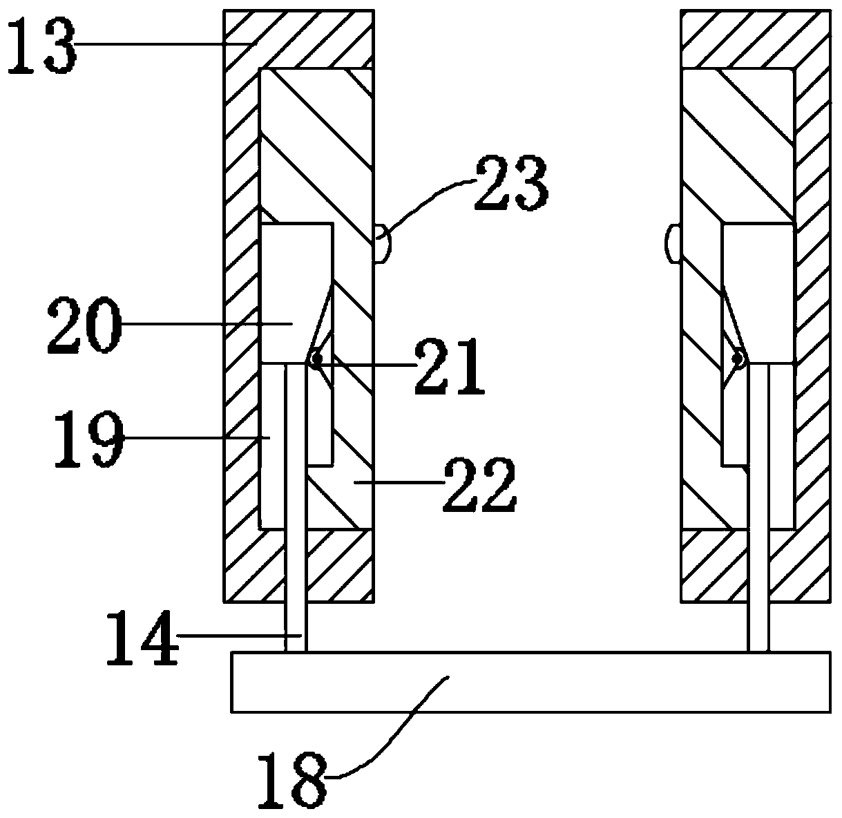
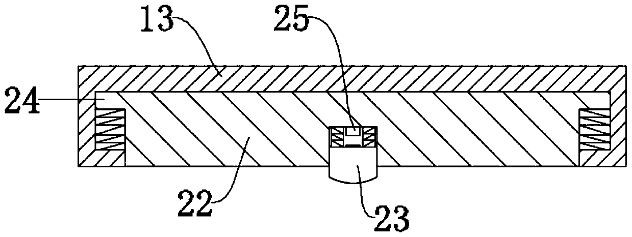
[0024] see Figure 1-6 , a kind of slaughtering equipment for animal husbandry, including a box body 1, one end of the box body 1 is arranged obliquely, and then it is convenient for livestock to board the box body 1, and a fixing component, a slaughtering component and a disinfection component are arranged on the box body 1, and the described The fixed assembly fixes the livestock on the box body; the fixed assembly includes a side plate 13, an extrusion block 22, a carrier plate 18 and a connecting rod 14, and the side plate 13 is fixedly connected to both sides of the box body 1, and the side plate 13 is provided with a placement groove 19, and the extrusion block 22 is slidably arranged on the placement groove 19, and the driving wheel 21 is rotated on the extrusion block 22. Between the extrusion block 22 and the side plate 13 The driving block 20 is slidingly arranged, and the driving block 20 acts on the driving wheel 21. The bottom of the driving block 20 is fixedly co...

Embodiment 2

[0032] In order to further improve the actual use effect of this device, this implementation has made the following improvements on the basis of Embodiment 1. The improvement is that the bottom plate of the box body 1 is rotatably equipped with a roller 2 with a brake function. Described roller 2 further improves that this device is easy to move, improves actual use effect.

[0033] The working principle of this embodiment: by installing rollers 2 on the bottom plate of the box body 1, the device is further improved to be easy to move, and the actual use effect is improved.


PUM


Abstract

The invention discloses slaughtering equipment for animal husbandry. The slaughtering equipment comprises a box body, one end of box body is tiltingly arranged, and a fixing assembly, a slaughter assembly and a disinfection assembly are arranged on the box body; side plates are fixedly connected to two sides of the box body; a placing groove is formed in each side plate; extrusion blocks are arranged on the placing grooves in a sliding manner; a driving wheel is rotationally mounted on each extrusion block; driving blocks are arranged between the extrusion blocks and the side plates in a sliding mode and act on the driving wheels, a connecting rod is fixedly connected to the bottom of each driving block, the other end of each connecting rod is fixedly connected to a carrier plate, an electric power component is arranged on each extrusion block, a slaughter assembly and a disinfection assembly are arranged on one side of the box body, and a supporting device is arranged between the carrier plate and the box body. The device is simple and reasonable in structure, and livestock can be effectively fixed through the weight of the livestock; meanwhile, in the livestock stunning state, the fixing effect can be further improved; the livestock is prevented from being fixed by manpower, and great application prospects are realized.

Description

technical field [0001] The invention relates to the field of animal husbandry, in particular to slaughter equipment for animal husbandry. Background technique [0002] Animal husbandry is the use of livestock and poultry and other animals that have been domesticated by humans, or the physiological functions of wild animals such as deer, musk deer, fox, mink, otter, quail, etc., through artificial feeding and breeding, so that they can transform the energy of plants such as pasture and feed The production department of livestock products such as meat, eggs, milk, wool, cashmere, hides, silk and medicinal materials for animals. Different from self-sufficient livestock breeding, the main characteristics of animal husbandry are centralized, large-scale, and profit-oriented production. Animal husbandry is an extremely important link in the material exchange between humans and nature. [0003] For now, in the existing animal husbandry, it is usually difficult to effectively fix ...

Claims


Application Information

Patent Timeline
IPC IPC(8): A22B1/00A22B3/06A22B5/06
CPCA22B1/00A22B3/06A22B5/06
Inventor 沈飞红
Owner 沈飞红
Learn More