An intelligent ceramic filter for industrial production

A ceramic filter, intelligent technology, applied in the direction of mobile filter element filter, filtration separation, chemical instruments and methods, etc., can solve the problems of easy clogging of ceramic tubes, troublesome cleaning of impurities, weak filtering effect, etc., to ensure the cleaning effect. , Improve the usable cycle and prevent the filtering effect from weakening

Active Publication Date: 2021-12-31
DAQING HUALI MECHANICAL MFG
View PDF2 Cites 0 Cited by
  • Summary
  • Abstract
  • Description
  • Claims
  • Application Information

AI Technical Summary

Problems solved by technology

[0003] The currently used ceramic filter, in the process of use, directly presses the filtrate into the interior of the ceramic tube with high pressure. At this time, the filtered impurities are left inside the ceramic tube, which is easy to block the ceramic tube. This further affects the filtering effect of the ceramic tube, making the filtering effect gradually weaken over time, which requires frequent cleaning. Generally, high-pressure back-blowing is used to clean it, and high-pressure gas is used to blow air from the outside of the ceramic tube to the inside. , and then make the internal impurities fall off, and remove the impurities inside the ceramic tube. This method is more troublesome, which reduces the work efficiency. Moreover, when filtering some liquids, the cleaning of impurities inside the ceramic tube is more troublesome. It is necessary to make the impurities attached to the ceramic tube The impurities on the inner side can only be cleaned by backflushing after drying
[0004] However, in the process of backflushing, there will inevitably be more impurities attached to the original feed pipe, which cannot be removed better, which will affect the effect of the next filtration and add unnecessary burden to the filter

Method used


Image

  • An intelligent ceramic filter for industrial production
  • An intelligent ceramic filter for industrial production
  • An intelligent ceramic filter for industrial production

Examples


Embodiment Construction

[0022] The following will clearly and completely describe the technical solutions in the embodiments of the present invention with reference to the accompanying drawings in the embodiments of the present invention. Obviously, the described embodiments are only some, not all, embodiments of the present invention. Based on the embodiments of the present invention, all other embodiments obtained by persons of ordinary skill in the art without making creative efforts belong to the protection scope of the present invention.

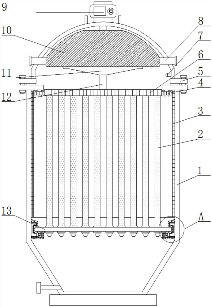
[0023] see Figure 1-6 , an intelligent ceramic filter for industrial production, comprising a device housing 1, a device housing 1, a device top cover 5 is movably installed on the top of the device housing 1, a pressure detector 7 is fixedly installed on the side of the inner cavity of the device top cover 5, and the device The top of the top cover 5 is fixedly equipped with a PLC controller 9, the top of the device top cover 5 inner cavity is movably instal...


PUM


Abstract

The invention relates to the technical field of filtering equipment, and discloses an intelligent ceramic filter for industrial production, comprising a device housing, the device housing, a device top cover movably installed on the top of the device housing, and an inner cavity of the device top cover A pressure detector is fixedly installed on the side of the device, a PLC controller is fixedly installed on the top of the top cover of the device, a rotating shaft is movably installed on the top of the inner cavity of the top cover of the device, and a collector is fixedly installed on the front of the inner cavity of the top cover of the device. flow chamber. The intelligent ceramic filter for industrial production, by setting the collecting chamber, curved pipe, connecting plate and swirl vane, makes the high-pressure liquid entering the device drive the rotating shaft to rotate, so that the ceramic filter tube is filtered. Rotate, so that the impurities cannot better adhere to the surface of the ceramic filter tube, thereby preventing the surface of the ceramic filter tube from adhering a large amount of impurities, blocking the ceramic filter tube, and preventing the filtering effect from weakening.

Description

technical field [0001] The invention relates to the technical field of filtering equipment, in particular to an intelligent ceramic filter for industrial production. Background technique [0002] The ceramic filter is a porous body that has two end faces and an outer peripheral face and separates the partition wall to form a plurality of main passages of the purified fluid from one end face to the other end face, and is arranged in the main passage. The filter membrane on the wall surface is formed, and flows into the main flow through an opening on the side of the end face, and the fluid to be purified passes through the filter membrane and the inside of the porous body to be purified, and is taken out as a purified fluid from the outer peripheral surface of the porous body, or The fluid to be purified passes through the interior of the porous body and the filter membrane to be purified by flowing in through the outer peripheral surface of the porous body, and is taken out ...

Claims


Application Information

Patent Timeline
Patent Type & Authority Patents(China)
IPC IPC(8): B01D33/37B01D33/56B01D33/80
CPCB01D33/37B01D33/56B01D33/80
Inventor 朱义法
Owner DAQING HUALI MECHANICAL MFG
Why Eureka
Try Eureka