
Paper gift bag cutting device

A gift bag and paper technology, which is applied in the field of paper gift bag interception devices, can solve the problems such as the position of the opening hole is not centered, the efficiency of opening the hand hole is low, etc., and the effect of high interception efficiency is achieved.

Inactive Publication Date: 2020-08-18
谭灯辉
View PDF8 Cites 3 Cited by
  • Summary
  • Abstract
  • Description
  • Claims
  • Application Information

AI Technical Summary

Problems solved by technology

[0003] In order to overcome the disadvantages of the existing paper gift bag production device, the efficiency of opening the handle hole is low, the position of the hole is not centered, and there is a phenomenon that the discarded part is slightly connected to the paper gift bag. The technical problem of the present invention is to provide A paper gift bag intercepting device with high efficiency, centered hole position interception and no waste residue

Method used


Image

  • Paper gift bag cutting device
  • Paper gift bag cutting device
  • Paper gift bag cutting device

Examples


Embodiment 1

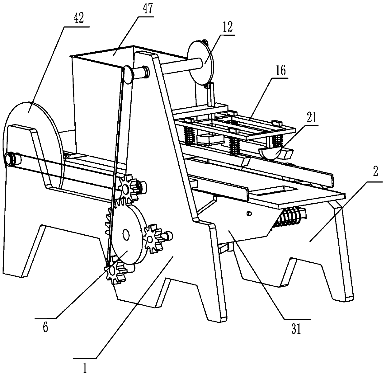
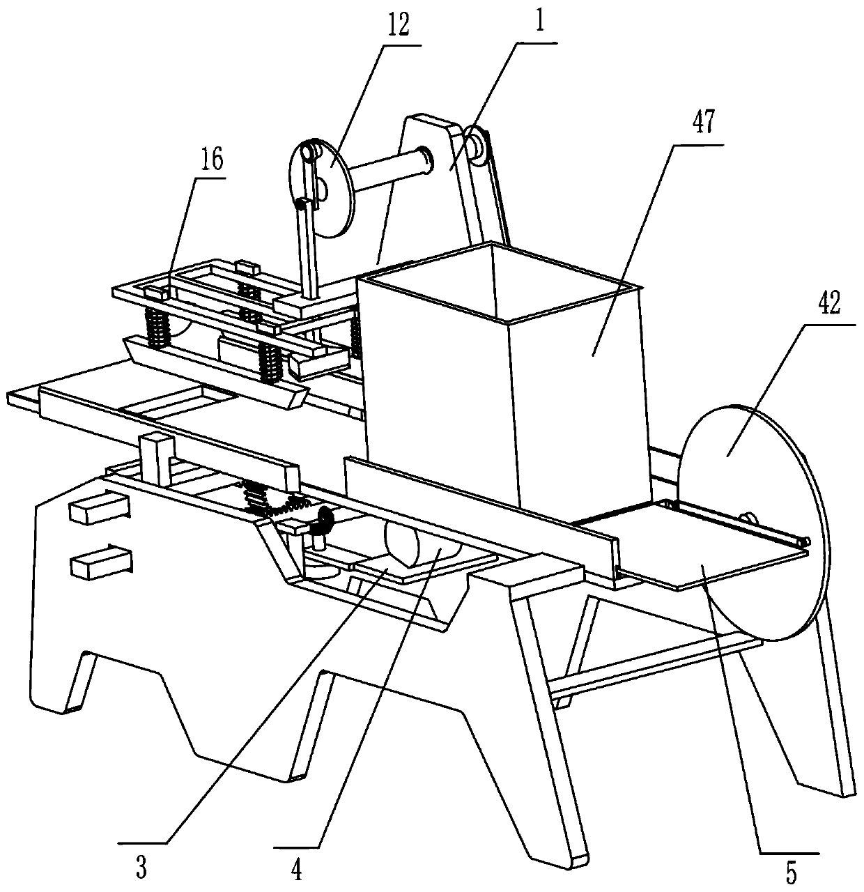
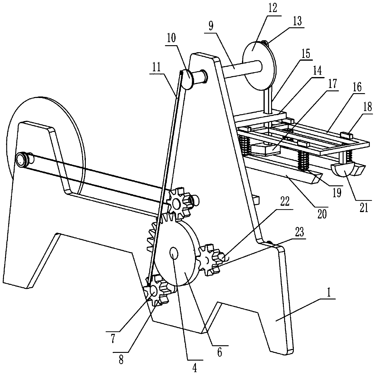
[0018] A paper gift bag intercepting device, such as Figure 1-5 As shown, it includes front support 1, rear support 2, supporting plate 3, motor 4, machine table 5, sector gear 6, first rotating shaft 7, first gear 8, upper rotating shaft 9, first turntable 10, connecting Rod one 11, second turntable 12, connecting rod two 13, guide plate 14 and descending body 15 and intercepting mechanism, described front support 1 is fixedly installed with pallet 3 by welding, and described motor 4 is installed on the pallet On the plate 3, the machine table 5 is fixedly installed on the rear support 2 by welding, the sector gear 6 is installed on the output shaft of the motor 4, and the first rotating shaft 7 is installed on the front support 1 through a bearing. Above, the first gear 8 is installed on one end of the first rotating shaft 7 and meshes with the sector gear 6, the upper rotating shaft 9 is installed on the upper right part of the front bracket through a bearing, and the firs...

Embodiment 2

[0020] On the basis of Example 1, such as Figure 1-5 As shown, the intercepting mechanism capable of intercepting paper gift bags includes a down frame 16, a cutter 17, a connecting body 18, a first spring 19, a trapezoidal pressing block 20 and an ejection block 21, and the down frame 16 passes through The way of welding is fixedly installed on the descending body 15, the cutter 17 is fixedly installed on one end of the descending body 15 by welding, and the four connecting bodies 18 are slidably installed on the descending frame 16 and the connecting body 18 can move 16 slides up and down, and the two trapezoidal pressing blocks 20 that can squeeze the paper gift bag are fixedly installed on the lower end of the connecting body 18 by welding, one end of the first spring 19 is installed on the down frame 16, and the other end is installed on the trapezoidal On the pressure block 20 and passed through by the connecting body 18, the ejection block 21 is fixedly installed on th...


PUM


Abstract

The invention relates to the field of paper gift bag processing, in particular to a paper gift bag cutting device. The technical problem to be solved by the invention is to provide the paper gift bagcutting device which is high in efficiency, centered in hole site cutting and free of waste part residues. The paper gift bag cutting device comprises a front support, a rear support, a supporting plate, a motor, a machine table, a sector gear, a first rotating shaft, a first gear, an upper rotating shaft, a first rotating disc, a first connecting rod, a second rotating disc and the like. The supporting plate is installed on the front support, the motor is installed on the supporting plate, the machine table is installed on the rear support, and the sector gear is installed on an output shaftof the motor. According to the paper gift bag cutting device, the motor runs to drive a material pushing mechanism to push a gift bag out of a discharging frame, meanwhile, a cutter of the cutting device is driven to cut the paper gift bag, and an ejection block cleans cut residues.

Description

technical field [0001] The invention relates to the field of paper gift bag processing, in particular to a paper gift bag cutting device. Background technique [0002] A gift bag is a kind of packaging item, which refers to a bag used to hold and package gifts. When the paper gift bag is produced, it is necessary to open a handle hole to facilitate people to carry it. The existing paper gift bag production device has a low efficiency of opening the handle hole, and the position of the hole is not centered. After the gift bag is intercepted and opened, it is necessary to manually remove the intercepted paper block, so it is urgently needed for research and development. A paper gift bag intercepting device with high efficiency, centered hole position interception and no waste residue. Contents of the invention [0003] In order to overcome the disadvantages of the existing paper gift bag production device, the efficiency of opening the handle hole is low, the position of t...

Claims


Application Information

Patent Timeline
Patent Type & Authority Applications(China)
IPC IPC(8): B31B70/20B31B70/00B31B70/04B26D7/18
CPCB31B70/20B31B70/04B31B70/006B26D7/1818
Inventor 谭灯辉
Owner 谭灯辉
Learn More