Two-degree-of-freedom motion ornithopter

A flapping-wing aircraft and degree of freedom technology, applied in the field of flapping-wing aircraft, can solve problems such as complex flapping-wing motion range, complex and bulky flapping-wing mechanism, etc., so as to reduce complex and bulky problems, improve control, and increase torque Effect

Active Publication Date: 2020-08-18
NANJING UNIV OF AERONAUTICS & ASTRONAUTICS
View PDF5 Cites 3 Cited by
  • Summary
  • Abstract
  • Description
  • Claims
  • Application Information

AI Technical Summary

Problems solved by technology

The above two designs are relatively complex and the flapping wing movement range is small, and the existing one-degree-of-freedo

Method used


Image

  • Two-degree-of-freedom motion ornithopter
  • Two-degree-of-freedom motion ornithopter
  • Two-degree-of-freedom motion ornithopter

Examples


Embodiment Construction

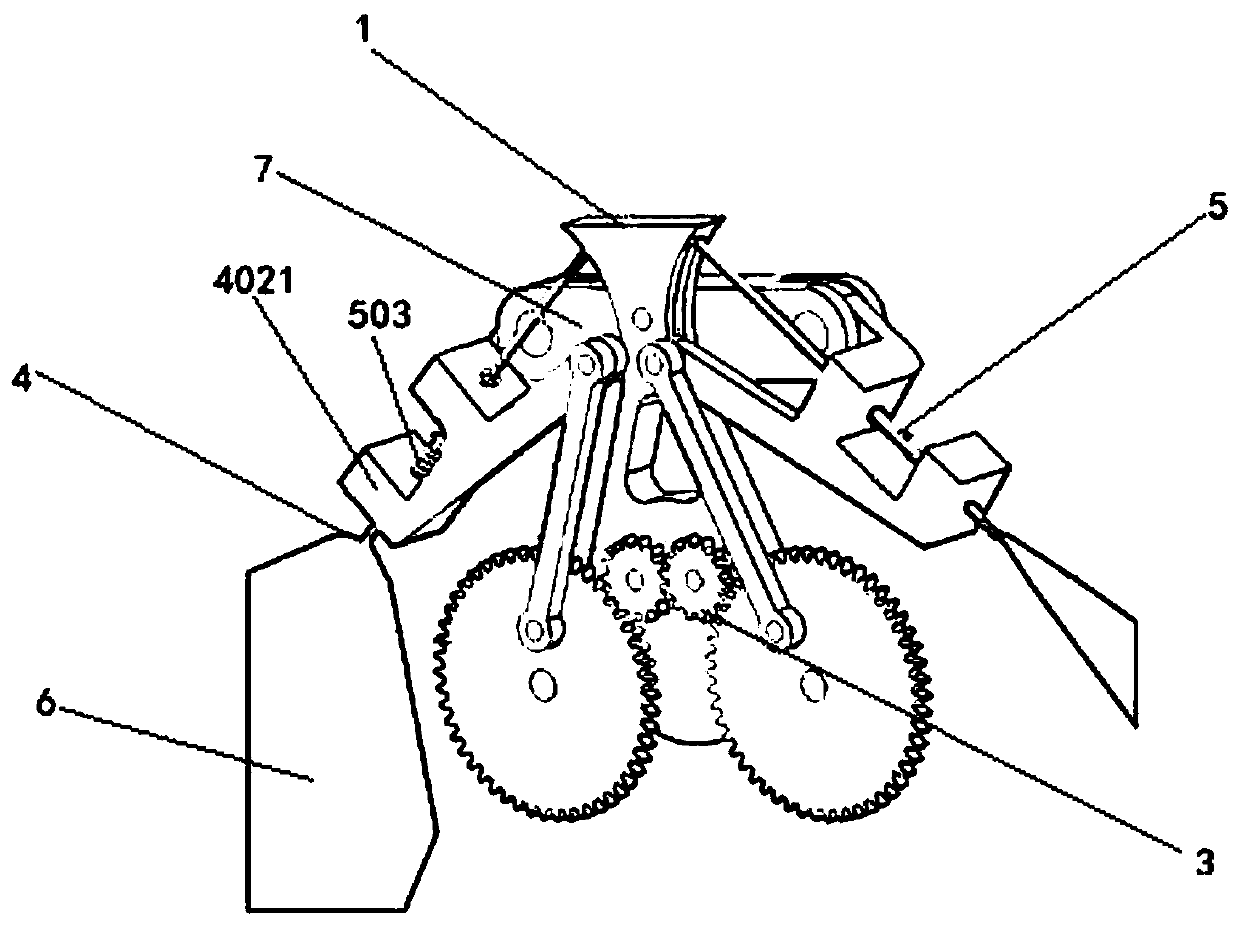
[0026] with instructions figure 1 The directions are up, down, left, right, front and back.

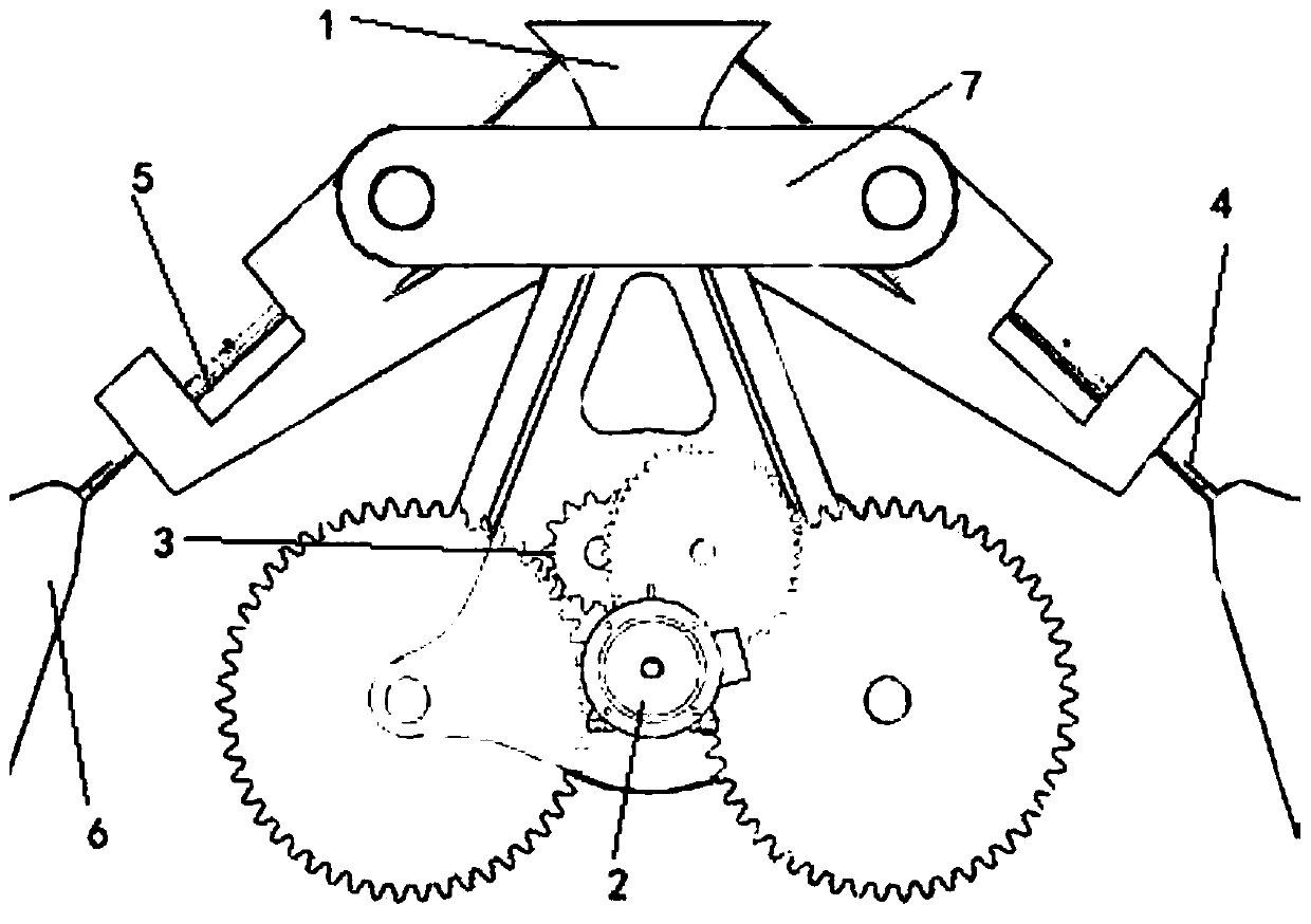
[0027] Such as Figure 1~2 , the motor 2 of the two-degree-of-freedom flapping-wing aircraft is fixedly connected to the frame 1, and the relative position of the motor 2 and the frame 1 does not change during the whole flapping-wing process. A pair of clapping mechanism 4 and a pair of rotating mechanism 5 are arranged on frame 1 both sides, and frame 1 back side is fixedly connected fixed rod 7, and fixed rod 7 is hinged with two projections one 4021 of clapping mechanism 4 respectively.

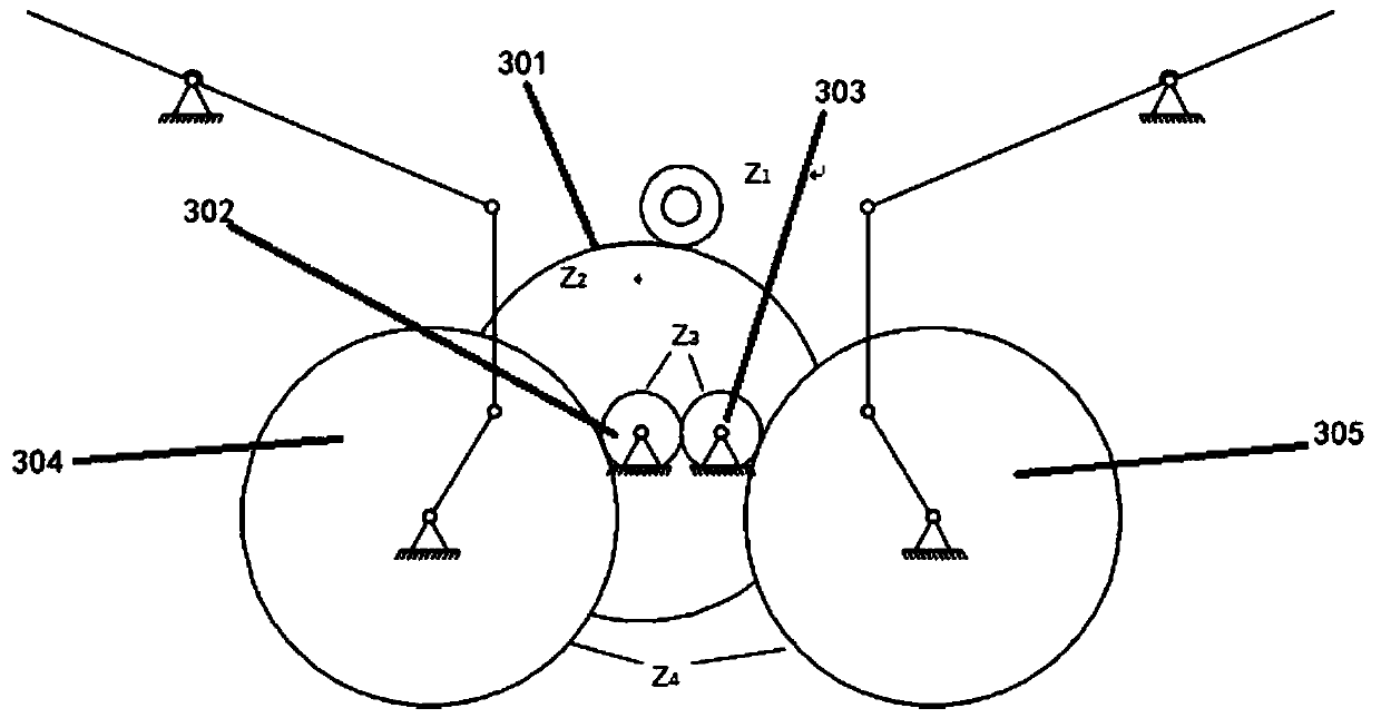
[0028] Such as image 3 , the motor shaft and gear one 201 are coaxially pivoted, the power of motor 2 is output through the motor shaft, and drives gear one 201 (Z 1 ) rotates, the gear two 301 (Z of the gear reduction mechanism 3 2 ) meshes with gear one 201, so gear two 301 rotates, and gear three 302 (Z 3 ) and gear two 301 are concentric gears, connected with a drive rod in the middle, g...


PUM


Abstract

The invention discloses a two-degree-of-freedom motion ornithopter. The ornithopter comprises a rack, a motor and a gear speed reducing mechanism; a pair of flapping mechanisms and a pair of rotatingmechanisms are arranged on the rack; the gear speed reducing mechanism is connected with the motor and the flapping mechanisms; chutes are symmetrically arranged in the side surfaces of the rack; eachrotating mechanism comprises a guide block, a guide rod and a spring, one end of the guide rod is fixedly connected with the guide block, the other end of the guide rod is connected with a bionic wing, the guide block can rotate along the semi-arc inner wall of the sliding groove at the upper end and the lower end of the sliding groove and drive the bionic wing to rotate, and the guide rod is provided with the spring, resets under the action of the spring and is connected with the flapping mechanism. The up-and-down movement of the guide block and the up-and-down flapping of the bionic wing form a 180-degree reverse phase. According to the invention, 100-degree flapping amplitude and 90-degree rotation amplitude can be realized, and the motion characteristic of periodic large-amplitude flapping of insect wings can be better simulated; the pair of flapping mechanisms and the pair of rotating mechanisms are used for realizing two-degree-of-freedom movement, so that the problems of complexity and heaviness of multi-connecting-rod or space mechanism driving rotation can be reduced.

Description

technical field [0001] The invention belongs to the field of aircraft, in particular to a two-degree-of-freedom flapping-wing aircraft. Background technique [0002] MAVs have three different flight modes: fixed-wing, rotary-wing and flapping-wing. Compared with conventional aircraft, the Reynolds number of MAV is very low, about 10 1 ~10 5 between. Within this Reynolds number range, none of the flying objects in nature, such as insects and birds, use fixed-wing or rotor-driven methods similar to mechanical flight to achieve flight. They all use flapping wings to achieve autonomous flight and have extremely high maneuverability Flexible and consumes little energy. [0003] Miniature flapping wing aircraft, also known as miniature flapping wing aircraft, miniature flapping wing aircraft, insect-like flying robot, etc., is designed by imitating the movement mechanism of insects in nature, and is one of the current research hotspots. The micro flapping wing aircraft can in...

Claims


Application Information

Patent Timeline
IPC IPC(8): B64C33/00B64C33/02
CPCB64C33/00B64C33/02Y02T50/60
Inventor 王姝歆熊凡陈国平金宝刘润
Owner NANJING UNIV OF AERONAUTICS & ASTRONAUTICS
Why Eureka
Try Eureka