Conveying equipment and conveying method
What is Al technical title?
Al technical title is built by PatSnap Al team. It summarizes the technical point description of the patent document.
A material conveying and equipment technology, applied in the field of material conveying equipment, can solve the problems of low degree of automation of pick and place operations, easy tilting of materials to be conveyed, affecting the smoothness of conveying, etc.
Active Publication Date: 2021-09-24
SUZHOU BECKE ELECTRIC TECH CO LTD
View PDF5 Cites 0 Cited by
Summary
Abstract
Description
Claims
Application Information
AI Technical Summary
This helps you quickly interpret patents by identifying the three key elements:
Problems solved by technology
Method used
Benefits of technology
Problems solved by technology
[0007] How to solve the problem of easy inclination and offset of the materials to be transported during the material transport process based on the synchronous and stable transport mode, so as not to greatly affect the smoothness of the transport, and to solve the automation of the pick-and-place operation of the materials to be transported Low, and a lot of manual participation is required, so as not to greatly affect the convenience of pick-and-place operations
Method used
Image
Click on the blue label to locate the original text in one second.
Reading with bidirectional positioning of images and text.
Examples
Embodiment Construction
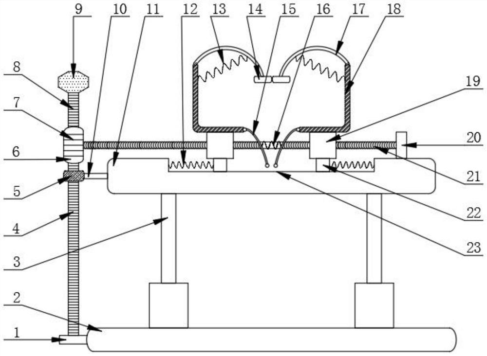
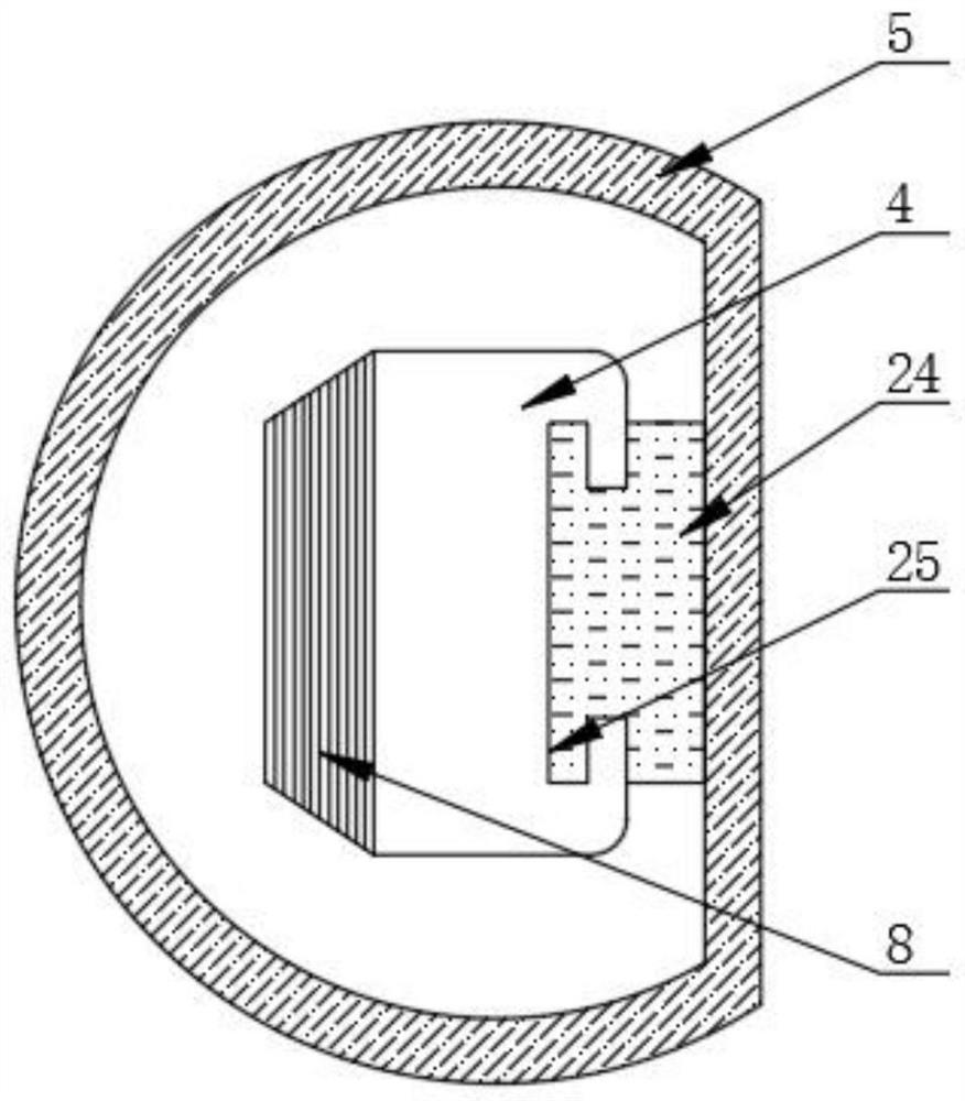
[0027] Such as Figure 1-2 As shown, the conveying equipment includes support block 1, bottom plate 2, electric push rod 3, column 4, collar 5, knob 6, first tooth groove 7, second tooth groove 8, wear-resistant rubber block 9, connecting rod 10. Fixed plate 11, first telescopic spring 12, second telescopic spring 13, pad 14, first elastic rod 15, third telescopic spring 16, second elastic rod 17, L-shaped splint 18, threaded sleeve 19, Block 20, threaded rod 21, slide block 22, chute 23, block 24 and draw-in groove 25, the top of bottom plate 2 is evenly provided with electric push rod 3, and the top of electric push rod 3 is fixed with fixed plate 11 by bolt;
[0028]The top center of the fixed plate 11 is provided with a chute 23, the inside of the chute 23 is correspondingly equipped with a slide block 22, and a second side wall is fixed by spot welding between one side of the slide block 22 and the adjacent side inner wall of the chute 23. A telescopic spring 12, the top...
PUM
Abstract
The invention discloses a material conveying device and a material conveying method, including a support block, a bottom plate, an electric push rod, a column, a collar, a knob, a first tooth groove, a second tooth groove, a wear-resistant rubber block, a connecting rod, a fixing plate, The first telescopic spring, the second telescopic spring, the spacer, the first elastic rod, the third telescopic spring, the second elastic rod, the L-shaped splint, the threaded sleeve, the block, the threaded rod, the slider, the chute, the block and the card slot, the top of the bottom plate is uniformly provided with an electric push rod, and the top of the electric push rod is fixed with a fixed plate by bolts; the present invention is based on the relationship between the block and the slot, the column and the knob, and the threaded sleeve and the threaded rod. The combined synchronous conveying method and the synchronous conveying method in which the upper and lower sides of the material to be conveyed and the two sides are gradually clamped are used to solve the problems that the materials to be conveyed are easy to tilt and shift during the conveying process, which greatly improves the conveying efficiency. Smoothness.
Description
technical field [0001] The invention relates to the technical field of conveying equipment, in particular to conveying equipment and a conveying method. Background technique [0002] In the document whose publication number is CN109205176A, the aluminum alloy materials of different sizes are only blocked according to the movable baffle plate, so as to prevent the material from falling downward during the climbing process of conveying materials, so that the plates can be conveyed in an orderly manner. And according to the buffer protection pad to protect the conveying aluminum alloy material, prevent the outer surface of the conveyor belt from being damaged, greatly prolonging the service life of the conveyor belt, and the second movable support rod of the conveying device is carried out by the set extension rod Extended so that it can be adapted to different working heights; [0003] However, in the process of conveying materials, there are still situations where the materi...
Claims
Application Information
Patent Timeline
Application Date:The date an application was filed.
Publication Date:The date a patent or application was officially published.
First Publication Date:The earliest publication date of a patent with the same application number.
Issue Date:Publication date of the patent grant document.
PCT Entry Date:The Entry date of PCT National Phase.
Estimated Expiry Date:The statutory expiry date of a patent right according to the Patent Law, and it is the longest term of protection that the patent right can achieve without the termination of the patent right due to other reasons(Term extension factor has been taken into account ).
Invalid Date:Actual expiry date is based on effective date or publication date of legal transaction data of invalid patent.