A kind of probe structure used in wat detection machine

A detection machine and probe technology, applied in the field of probe structure, can solve the problems of low motion efficiency, complex assembly, complex maintenance, etc., and achieve the effects of small moving load, avoiding complex assembly, and improving contact accuracy

Active Publication Date: 2019-11-29
WUHAN XINXIN SEMICON MFG CO LTD
View PDF3 Cites 0 Cited by
  • Summary
  • Abstract
  • Description
  • Claims
  • Application Information

AI Technical Summary

Problems solved by technology

[0002] The mainstream scheme of the existing WAT inspection machine is: the probe is fixed, and when the contact to be detected on the wafer is aligned with the probe in the vertical direction, the micro-displacement mechanism drives the wafer to move vertically upward under the action of the motor, so as to Realize the contact between the probe and the contact point to be detected on the wafer to complete the detection; some of the micro-displacement mechanisms use screw guide rails, and some use cams, which are complex in assembly, low in motion efficiency, easy to wear, and complex in maintenance

Method used


Image

  • A kind of probe structure used in wat detection machine

Examples


Embodiment Construction

[0026] The principles and features of the present invention are described below in conjunction with the accompanying drawings, and the examples given are only used to explain the present invention, and are not intended to limit the scope of the present invention.

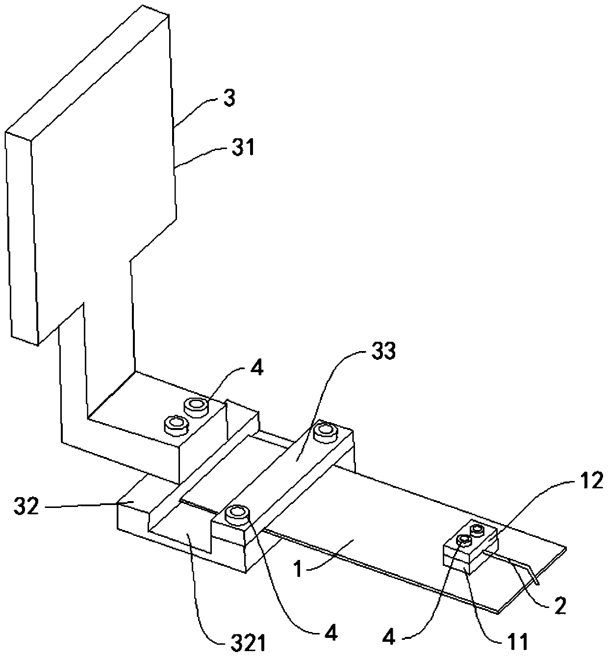
[0027] Such as figure 1 As shown, a probe structure for a WAT ​​detector includes a piezoelectric ceramic bending actuation piece 1, one end of the piezoelectric ceramic bending actuation piece 1 is provided with a probe 2, and the other end is arranged on a fixed bracket 3 ; The positive and negative connections of the piezoelectric ceramic bending actuator piece 1 are electrically connected to the power supply through wires, and the power supply is electrically connected to the controller.

[0028] The fixed bracket 3 includes a fixed plate 31 and a connecting plate 32; one end of the connecting plate 32 is connected to the fixed plate 31, and the other end cooperates with the first fixed cover plate 33 above it t...


PUM


Abstract

The invention relates to a probe structure for a WAT ​​detection machine, comprising a piezoelectric ceramic bending actuation piece, one end of the piezoelectric ceramic bending actuation piece is provided with a probe, and the other end is arranged on a fixed support; the pressure The positive and negative connections of the electroceramic bending actuating piece are electrically connected to a power supply through wires, and the power supply is electrically connected to a controller. The beneficial effects of the present invention are: the piezoelectric ceramic bending actuating piece is used to drive the probe to move downward instead of the micro-displacement mechanism in the prior art to drive the wafer disk upward under the action of the motor; effectively avoiding the complicated assembly of the micro-displacement mechanism, the movement Low efficiency, easy wear, and complicated maintenance; and the probe moves with a small moving load, which effectively improves the contact accuracy between the probe and the contact to be tested on the wafer, and improves test performance.

Description

technical field [0001] The invention relates to the technical field of semiconductors, in particular to a probe structure for a WAT ​​(Wafer Acceptance Test) inspection machine. Background technique [0002] The mainstream scheme of the existing WAT inspection machine is: the probe is fixed, and when the contact to be detected on the wafer is aligned with the probe in the vertical direction, the micro-displacement mechanism drives the wafer to move vertically upward under the action of the motor, so as to Realize the contact between the probe and the contact point to be detected on the wafer to complete the detection; some of the micro-displacement mechanisms use screw guide rails, and some use cams. The assembly is complicated, the movement efficiency is low, easy to wear, and the maintenance is complicated. Contents of the invention [0003] The object of the present invention is to provide a probe structure for a WAT ​​testing machine to solve the above-mentioned proble...

Claims


Application Information

Patent Timeline
Patent Type & Authority Patents(China)
IPC IPC(8): H01L21/66
CPCH01L22/14
Inventor 黄炜张晓敏舒晶徐静静
Owner WUHAN XINXIN SEMICON MFG CO LTD
Why Eureka
Try Eureka