Rapid pressure release valve and integrated type diaphragm pump adopting rapid pressure release valve assembly

A pressure relief valve and diaphragm pump technology, applied to pumps with flexible working elements, liquid displacement machines, pumps, etc., can solve the problem of difficult control of channel cross-sectional area, uncontrollable ventilation volume, uncontrollable depressurization speed, etc. question

Pending Publication Date: 2020-08-18
XIAMEN CONJOIN ELECTRONICS TECH
View PDF2 Cites 0 Cited by
  • Summary
  • Abstract
  • Description
  • Claims
  • Application Information

AI Technical Summary

Problems solved by technology

[0004] Careful analysis of these rapid pressure relief structures, it is not difficult to find that there is such a problem: the upper and lower areas of these relief valves 200 are basically the same, and when inflated, they are simply relying on the pressure difference (pressure difference) between the middle air chamber 100 and the top air chamber 600. To block the pressure relief port 300, that is, the inflation pressure must be large enough to lift the air relief valve 200 upwards to block the pressure relief port 300
but, figure 1 The decomp

Method used


Image

  • Rapid pressure release valve and integrated type diaphragm pump adopting rapid pressure release valve assembly
  • Rapid pressure release valve and integrated type diaphragm pump adopting rapid pressure release valve assembly
  • Rapid pressure release valve and integrated type diaphragm pump adopting rapid pressure release valve assembly

Examples


Embodiment 3

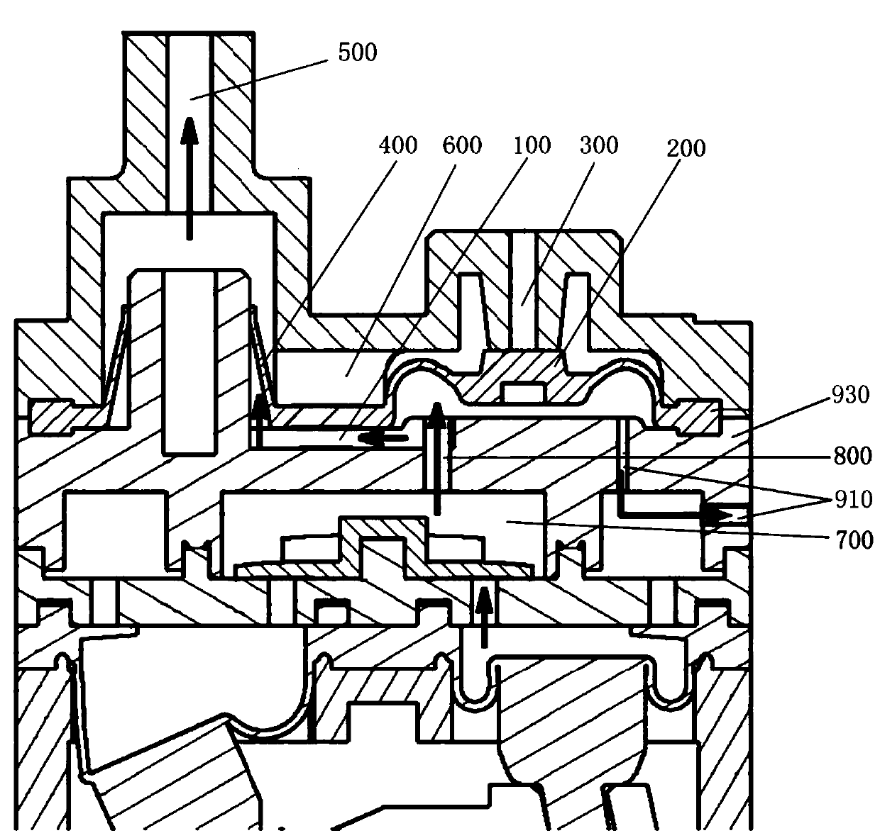
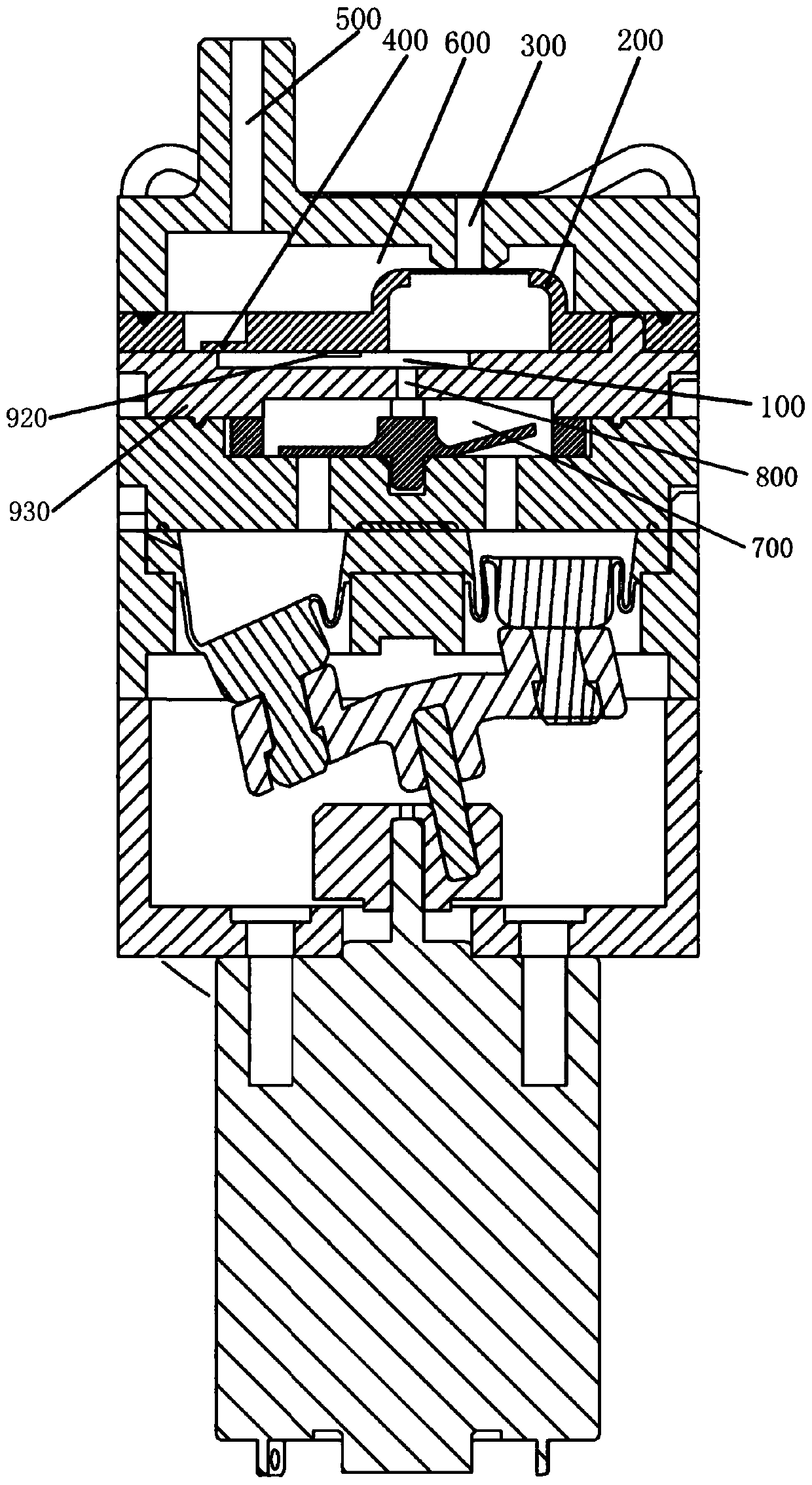
[0078] The structure of the integrated diaphragm pump in embodiment three is as follows: Figure 28 As shown, it has a motor 7, a base 8, an eccentric wheel 71, a drive shaft 72, a support frame 73, an air bag 61, an air bag seat 6, a valve seat 62, an air outlet valve 63, a diaphragm positioning plate 5, and the above-mentioned quick pressure relief valve assembly and top cover 1. The motor 7 is installed on the base 8, and the airbag seat 6 is assembled on the base 8. Air bag 61 can specifically have two, and air bag 61 is installed on the air bag seat 6, and the bottom of air bag 61 is connected with support frame 73, and motor 7 drives air bag 61 action by eccentric wheel 71, drive shaft 72 and support frame 73 and inflates. The improvement points are: the valve seat 62, the diaphragm positioning plate 5, the above-mentioned quick pressure relief valve assembly and the upper cover 1 are sequentially assembled on the airbag seat 6. The difference between the third embodim...


PUM


Abstract

The invention discloses a rapid pressure release valve assembly installed on the lower side of an upper cover of a pump. The rapid pressure release valve assembly comprises a gas outlet diaphragm, a gas discharge diaphragm and a diaphragm pressing plate. The gas outlet diaphragm forms a bulged diaphragm. The top of the bulged diaphragm is provided with a first center sheet used for corresponding to a pressure release hole of the upper cover. The diaphragm pressing plate covers the bulged diaphragm of the gas outlet diaphragm. The top of the diaphragm pressing plate is provided with a center hole allowing the first center sheet to be exposed. The gas discharge diaphragm is fixed to the top of the diaphragm pressing plate. The diaphragm discharge diaphragm is provided with a second center sheet used for corresponding to the pressure release hole of the upper cover. The second center sheet penetrates through the center hole of the diaphragm pressing plate to be corresponding to the firstcenter sheet. The upper surface area of the second center sheet is smaller than the lower surface area of the first center sheet. The gas discharge diaphragm, the diaphragm pressing plate and the bulged diaphragm define a normal pressure cavity communicating with the atmosphere. The invention further discloses a diaphragm pump adopting the rapid pressure release valve assembly. According to the rapid pressure release valve assembly, the difference between the gas pressure acting on the first center sheet and the gas pressure acting on the second center sheet is utilized to control opening andclosing of the pressure release hole, a traditional technology of only depending on gas pressure to conduct control is replaced, and rapid gas discharge and stable gas charge are achieved.

Description

technical field [0001] The invention relates to the technical field of diaphragm pumps, in particular to the structure of a quick relief valve assembly and an integrated diaphragm pump using the quick relief valve assembly. Background technique [0002] In medical product sphygmomanometers, especially booster sphygmomanometers, an air pump and a normally closed solenoid valve are normally used. When the inflation reaches a certain air pressure value, the solenoid valve is energized and opened to release the pressure. In order to reduce the cost, the solenoid valve is omitted, but the function is integrated into the air pump. Some operators have specially developed an integrated pump that can realize rapid pressure relief. [0003] Such as: CN201510505369.2 and CN201821850946.7, see figure 1 and figure 2 . When the pump body is inflated, the gas released by the air bag enters the air outlet cavity 700, and the gas enters an intermediate air chamber 100 through an air inl...

Claims


Application Information

Patent Timeline
IPC IPC(8): F04B39/10F04B45/04F04B45/047F16K17/26F16K27/02
CPCF04B39/10F04B45/045F04B45/047F16K17/26F16K27/0236
Inventor 颜宏
Owner XIAMEN CONJOIN ELECTRONICS TECH
Why Eureka
Try Eureka