Unlock instant, AI-driven research and patent intelligence for your innovation.
A solar radiometer and spectrum observation system and control method
What is Al technical title?
Al technical title is built by PatSnap Al team. It summarizes the technical point description of the patent document.
A technology of solar radio and control method, applied in the field of solar radio radiometer
Active Publication Date: 2021-06-04
SHANDONG UNIV
View PDF0 Cites 0 Cited by
Summary
Abstract
Description
Claims
Application Information
AI Technical Summary
This helps you quickly interpret patents by identifying the three key elements:
Problems solved by technology
Method used
Benefits of technology
Problems solved by technology
[0009] In view of the deficiencies in the prior art, the purpose of the present invention is to provide a solar radiometer and spectrum observation system and control method, aiming at the reduction in sensitivity caused by the structural gain of the solar radiometer observation system in radio astronomy and the reduction in time resolution caused by integration In this case, an improved observation structure is proposed, which can be used as a spectrum observation device or a radiometer observation, and can flexibly adjust the integration bandwidth, and at the same time use the form of sliding integration to ensure the time resolution of the original data of the spectrum and radiometer
Method used
Image
Click on the blue label to locate the original text in one second.
Reading with bidirectional positioning of images and text.
Examples
Embodiment 1
[0040] This embodiment provides a solar radiometer and spectrum observation system, which adopts ADC+FPGA with high sampling bandwidth and high sampling rate for signal processing, and adopts zero balance calculation by switching to eliminate gain influence.
[0041] Table 1 Comparison of structural performance of three radiometers
[0042]
[0043] Table 1: T a is the antenna output noise temperature, T r is the receiver system noise temperature, T ref To refer to the load noise temperature, G is the system gain, B is the system bandwidth (the bandwidth before detection, usually more than ten MHz), and τ is the system pre-integration time.
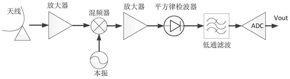
[0044] full power radiometer figure 1 As shown, the system structure is composed of antenna, video amplifier, mixer, intermediate frequency amplifier, square law detector, low-pass filter, ADC and so on. The square law detector converts the RF power signal output by the intermediate frequency amplifier into a voltage signal. The d...
Embodiment 2
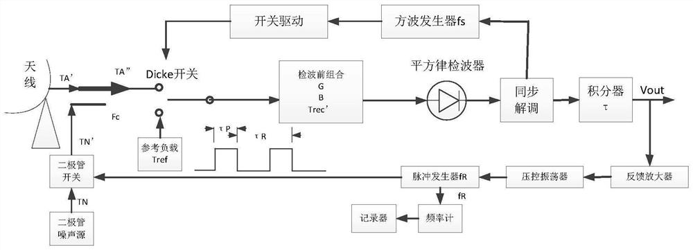
[0051] This embodiment provides a solar radiometer and spectrum observation control method, using the solar radiometer and spectrum observation system described in Embodiment 1, the control process is as follows Figure 8 Shown:
[0052] (1) The upper computer sends parameters to control the square wave generator and synchronization module, thereby controlling the system integration time τ and integration bandwidth B.
[0053] (2) The square wave generator and synchronization module adjust the pulse duty cycle according to the total integration time required by the system and the output value of the final balance judgment, thereby adjusting the ratio time between the antenna and the reference input.
[0055] Among them, τ is the system integration time, τ 21 For the switching pulse located at the antenna and the reference load T ref1 The turn-on time of the antenna when between, τ 1 is the reference load T ref1 c...
PUM
Abstract
The invention discloses a solar radio radiometer, a spectrum observation system and a control method. Converter, FPGA signal processing module and upper computer; wherein, the switch is connected to two different reference loads to provide brightness temperature calibration, and the switch is connected to the antenna, and the output frequency of the antenna and the reference source is adjusted according to the balance judgment or duty cycle. The present invention aims at reducing the sensitivity caused by the structural gain of the solar radio radiometer observation system in radio astronomy and reducing the time resolution caused by the integration, and proposes an improved zero-balanced Dick-type observation structure, which can be used as a spectrum observation device or as a radiometer observation , and the calibration principle and process are given, the integration bandwidth can be flexibly adjusted, and the form of sliding integration is used to ensure the time resolution of the original data of the spectrum and radiometer.
Description
technical field [0001] The invention relates to the field of solar radio radiometers, in particular to a solar radio radiometer, a spectrum observation system and a control method. Background technique [0002] Any object emits electromagnetic waves to the outside world under certain conditions. As a high-sensitivity electromagnetic wave detection device, radiometers are widely used in fields such as space weather, ground remote sensing, target detection and identification, and security inspection. The two most common and used types are The radiometer structure is: full power radiometer, Dicke radiometer and other types of radiometers, among which Dicke radiometer is divided into balanced type and unbalanced type. [0003] The structure of the full power radiometer is simple, and the square law detector is directly used to convert the power signal into a voltage, and after passing through a low-pass filter (pre-integrator), the ADC is used for quantitative acquisition and up...
Claims
Application Information
Patent Timeline
Application Date:The date an application was filed.
Publication Date:The date a patent or application was officially published.
First Publication Date:The earliest publication date of a patent with the same application number.
Issue Date:Publication date of the patent grant document.
PCT Entry Date:The Entry date of PCT National Phase.
Estimated Expiry Date:The statutory expiry date of a patent right according to the Patent Law, and it is the longest term of protection that the patent right can achieve without the termination of the patent right due to other reasons(Term extension factor has been taken into account ).
Invalid Date:Actual expiry date is based on effective date or publication date of legal transaction data of invalid patent.

