Marine automatic cable laying robot

An automatic laying and robot technology, applied in the direction of cable laying equipment, etc., can solve the problems of wasting time and resources, low construction efficiency, etc., and achieve the effect of reducing work intensity, improving laying efficiency, and reducing human resource investment

Active Publication Date: 2020-08-18
SHANGHAI WAIGAOQIAO SHIP BUILDING CO LTD
View PDF16 Cites 2 Cited by
  • Summary
  • Abstract
  • Description
  • Claims
  • Application Information

AI Technical Summary

Problems solved by technology

[0002] At the current level of technology, the laying of marine cables is basically laid and pulled by manpower. The construction efficiency is very low, and it is a waste of time and resources.

Method used


Image

  • Marine automatic cable laying robot
  • Marine automatic cable laying robot

Examples


Embodiment Construction

[0021] The present invention will be further described below in conjunction with accompanying drawing.

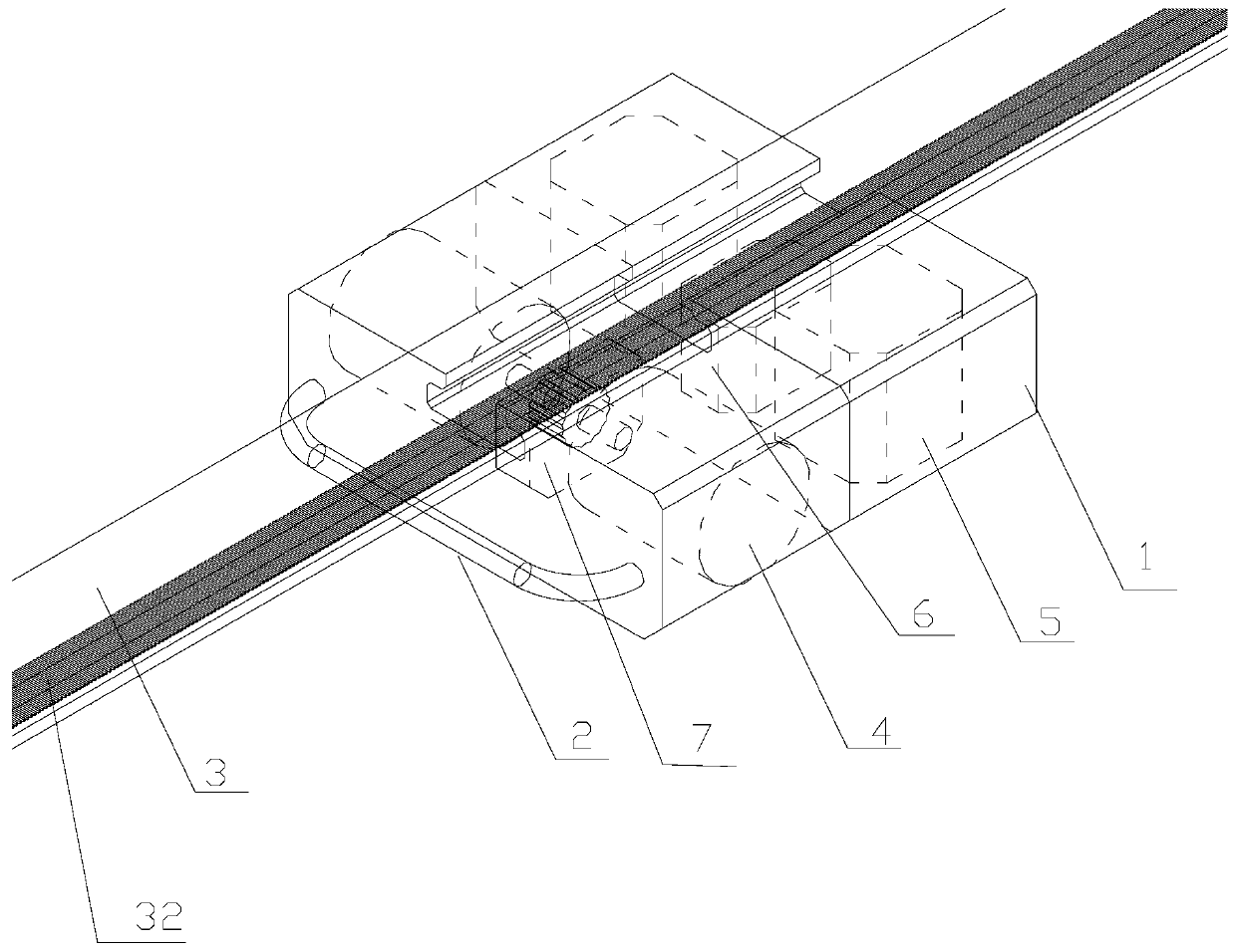
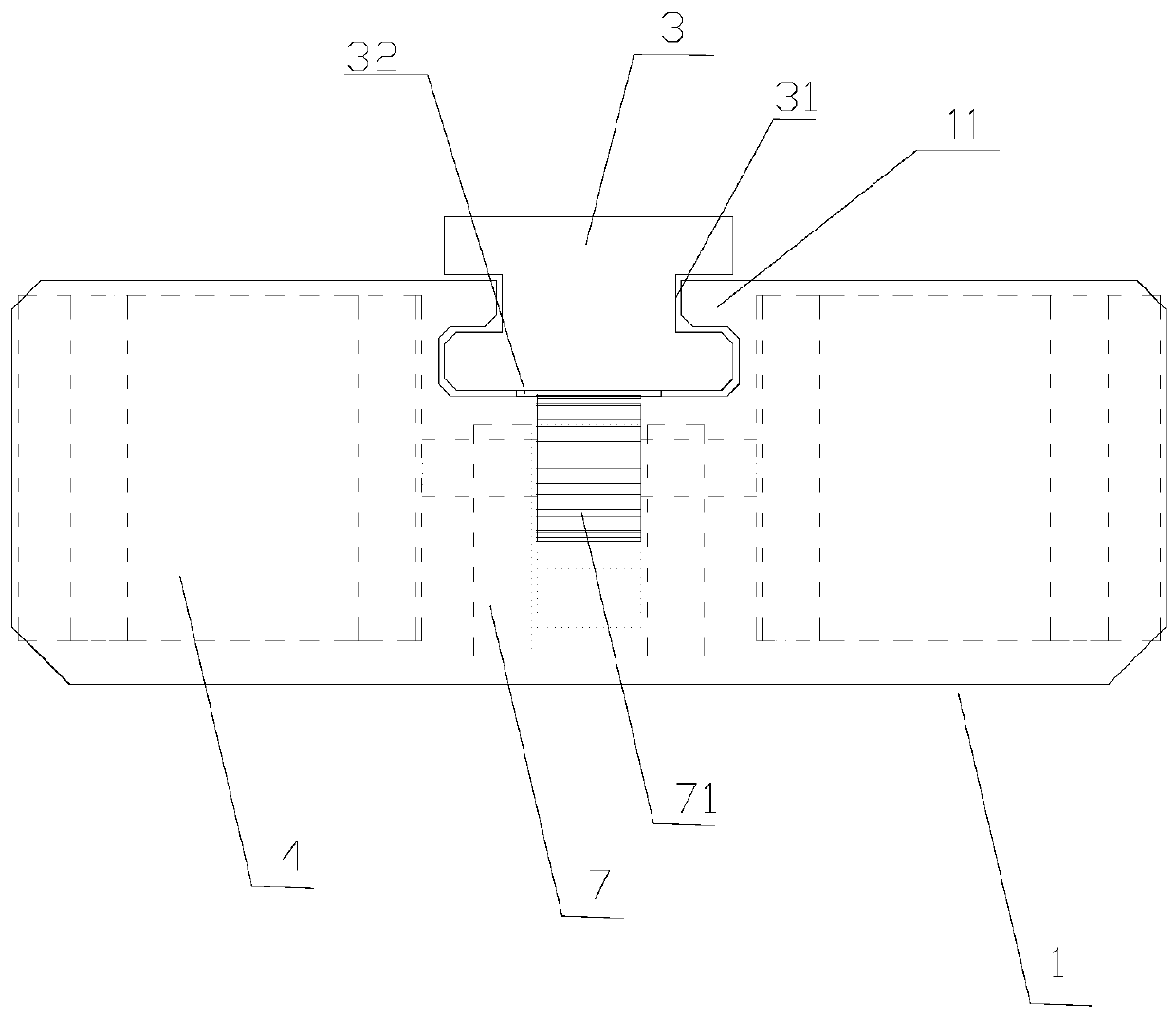
[0022] see figure 1 with figure 2 , The marine automatic cable laying robot of the present invention includes: an installation box 1, a cable binding fixture 2, a robot walking guide rail 3, a pair of motors 4, a pair of lithium batteries 5, a control module 6 and a motor gearbox 7.

[0023] The two sides of robot walking guide rail 3 have chute 31, and the bottom center is provided with rack track 32. The center of the installation box 1 is provided with a groove that fits with the walking guide rail 3 of the robot, and the two sides of the groove are provided with raised lines 11 that fit with two slide grooves 31 .

[0024] Two motors 4 are symmetrically fixed inside the installation box 1 on both sides of the robot walking guide rail 3 . The motor gearbox 7 is fixed inside the installation box 1 between the two motors 4, and is positioned directly below the robot wa...


PUM


Abstract

The invention discloses a marine automatic cable laying robot which comprises a mounting box, a cable binding fixing part, a robot walking guide rail, a pair of motors, a pair of lithium batteries, acontrol module and a motor gear box, chutes are formed in the two side faces of the robot walking guide rail, and a rack rail is arranged in the center of the bottom of the robot walking guide rail; and a groove matched with the robot walking guide rail is formed in the center of the mounting box, and protruding strips matched with the two chutes are arranged on the two side faces of the groove. The two motors are symmetrically fixed in the mounting box on the two sides of the robot walking guide rail; the motor gear box is fixed in the mounting box between the two motors and located under therobot walking guide rail, and a walking gear meshed with the rack rail is arranged at the top of the motor gear box; and the two lithium battery scales are fixed in the mounting box on the two sidesof the robot walking guide rail. Cable laying by on-site construction personnel can be replaced, and the on-site cable laying efficiency can be greatly improved.

Description

technical field [0001] The invention relates to a marine automatic cable laying robot. Background technique [0002] At the current level of technology, the laying of marine cables is basically laid and pulled by manpower. The construction efficiency is very low, and it is a waste of time and resources. Under such circumstances, if automatic laying can be realized, the construction will be greatly reduced. The input of personnel, and at the same time improve the efficiency of on-site construction. Contents of the invention [0003] The purpose of the present invention is to provide a marine automatic cable laying robot, which can replace on-site construction personnel to lay cables, and can greatly improve the efficiency of on-site cable laying. [0004] The technical scheme for realizing the above-mentioned purpose is: [0005] A marine automatic cable laying robot, including: installation box, cable binding fixture, robot walking guide rail, a pair of motors, a pair of...

Claims


Application Information

Patent Timeline
IPC IPC(8): H02G1/06
CPCH02G1/06
Inventor 王玉玺丁磊申慧忠韩睿
Owner SHANGHAI WAIGAOQIAO SHIP BUILDING CO LTD
Why Eureka
Try Eureka