Optical fiber dispensing device and flexible mesh-shaped optical fiber belt automatic production device

A technology of dispensing device and optical fiber, which is applied to the device, light guide, optics and other directions for coating liquid on the surface. Solve the effect of slow dispensing speed

Active Publication Date: 2020-08-21
WUHAN XINHAO INTELLIGENT TECH CO LTD
View PDF10 Cites 3 Cited by
  • Summary
  • Abstract
  • Description
  • Claims
  • Application Information

AI Technical Summary

Problems solved by technology

[0003] The purpose of the present invention is to provide an optical fiber dispensing device and automatic production equipment for flexible mesh optical fiber ribbon. complicated question

Method used


Image

  • Optical fiber dispensing device and flexible mesh-shaped optical fiber belt automatic production device
  • Optical fiber dispensing device and flexible mesh-shaped optical fiber belt automatic production device
  • Optical fiber dispensing device and flexible mesh-shaped optical fiber belt automatic production device

Examples


Embodiment 1

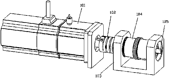
[0045] Such as figure 1 As shown, an optical fiber dispensing device includes a dispensing component and a driving component (such as a motor 101 ).

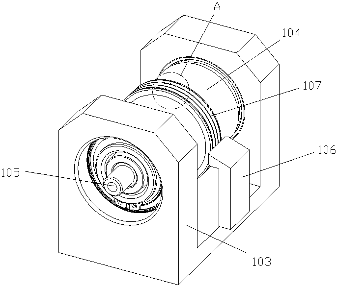
[0046] Such as figure 1 , 2 , 5, 7, and 8, the dispensing assembly includes a rotatable rotating shaft 104 and a fixed injection shaft 105, the rotating shaft 104 is a hollow structure with one end open, and the other end and the motor 101 pass through a coupling 102 connections. The rotating shaft 104 is sleeved on the glue injecting shaft 105 , the rotating shaft 104 is mounted on the fixing seat 103 through a bearing, and the glue injecting shaft 105 is fixedly connected with the fixing seat 103 .

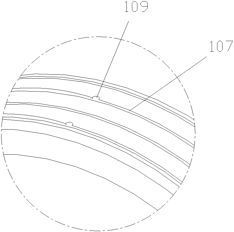
[0047] The rotating shaft 104 is provided with one or more axially parallel first dispensing holes 109 for connecting inside and outside. 1. When a plurality of first dispensing holes 109 are provided on the rotating shaft 104 (the preferred solution), such as Figure 5 , the first dispensing hole 109 is provided with four,...

Embodiment 2

[0052] In this embodiment, a squeegee 106 is added on the basis of the first embodiment, as figure 2 , 4 As shown, the squeegee 106 is fixedly installed on the fixed seat 103, and the squeegee 106 is matched with the outer surface of the rotating shaft 104 (including the limit groove 107), and is used to scrape off the centrifugal force when the rotating shaft 104 rotates at a high speed. The residual glue thrown out from the first glue dispensing hole 109.

Embodiment 3

[0054] This embodiment is an improvement made on the basis of the first embodiment.

[0055] Such as Figure 14-16 As shown, the limit groove 107 on the rotating shaft 104 is canceled, and an optical fiber positioning shaft 112 is added outside the rotating shaft 104, and the optical fiber positioning shaft 112 is sleeved on the outside of the rotating shaft 104; the rotating shaft 104 is installed on the fixed seat 103 through a bearing Above, the glue injection shaft 105 and the fiber positioning shaft 112 are fixedly connected with the fixed seat 103; the rotation shaft 104 is directly connected with the glue injection shaft 105 and the fiber positioning shaft 112 through bearings, and is sealed by a sealing ring.

[0056] When four first dispensing holes 109 are provided on the rotating shaft 104, four second dispensing holes 113 are arranged side by side on the upper side of the optical fiber positioning shaft 112, along with the rotating shaft 104 Rotating the first glu...


PUM


Abstract

The invention relates to the technical field of mesh belt optical fiber production devices, and specifically relates to an optical fiber dispensing device comprising a dispensing assembly. The dispensing assembly comprises a rotatable rotation shaft, a fixed glue injection shaft and a fixed optical fiber positioning shaft. The glue injection shaft is sleeved with the rotation shaft. The rotation shaft is sleeved with the optical fiber positioning shaft. One or multiple second dispensing holes which are side by side in the axial direction are formed in the optical fiber positioning shaft. A glue guide groove is formed in the outer surface of the glue injection shaft. A glue guide hole used for making the glue guide groove communicate with an external glue supply device is further formed inthe glue injection shaft. First dispensing holes corresponding to the second dispensing holes in a one-to-one manner are formed in the rotation shaft. When the rotation shaft rotates, the second dispensing holes and the glue guide groove are made to periodically communicate through the first dispensing holes. The optical fiber dispensing device has the characteristics of being high in dispensing speed and simple in structure, and the problems that in the prior art, the dispensing speed is low and device mechanisms are complex are effectively solved.

Description

technical field [0001] The invention relates to the technical field of mesh ribbon optical fiber production equipment, in particular to an optical fiber dispensing device and an automatic production equipment for flexible mesh optical fiber ribbons using the optical fiber dispensing device. Background technique [0002] At present, the traditional ribbon-shaped optical fiber is bonded with glue and then solidified. The optical fiber has a large volume, poor flexibility, no elasticity and a small bending radius, and it is easy to break or bend and deform during use. In order to solve the above problems, it is necessary to produce the current ribbon fiber into a mesh ribbon fiber (flexible mesh fiber ribbon), such as Figure 17 shown. It is to arrange a plurality of optical fiber core wires side by side, and use the connecting material to connect the plurality of optical fibers at the mesh nodes to form intermittent mesh nodes, which facilitates the separation of optical fiber...

Claims


Application Information

Patent Timeline
Patent Type & Authority Applications(China)
IPC IPC(8): B05C5/02B05C13/02B05D3/06B05C11/10G02B6/44
CPCB05C5/0241B05C11/10B05C13/02B05D3/06G02B6/448
Inventor 屈红军曹首科李明代杨帆杨涛柳其硕邵露曾旋焱吴国彪薛小鹏
Owner WUHAN XINHAO INTELLIGENT TECH CO LTD
Why Eureka
Try Eureka