
Ultrasonic probe piezoelectric wafer automatic glue-dispensing and chip-mounting machine

A piezoelectric chip and automatic glue dispensing technology, which is applied in the manufacture/assembly of piezoelectric/electrostrictive devices, devices for coating liquid on the surface, coating, etc., can solve the problem of poor mounting effect and poor dispensing effect , low degree of automation and other issues, to achieve the effect of high dispensing speed, convenient replacement and high degree of automation

Active Publication Date: 2019-04-16
WUHAN TEXTILE UNIV
View PDF4 Cites 3 Cited by
  • Summary
  • Abstract
  • Description
  • Claims
  • Application Information

AI Technical Summary

Problems solved by technology

[0003] The purpose of the present invention is to overcome the defects and problems of poor dispensing effect, poor mounting effect and low degree of automation in the prior art, and provide an ultrasonic probe pressure sensor with good dispensing effect, good mounting effect and high degree of automation. Electric chip automatic dispensing and placement machine

Method used


Image

  • Ultrasonic probe piezoelectric wafer automatic glue-dispensing and chip-mounting machine
  • Ultrasonic probe piezoelectric wafer automatic glue-dispensing and chip-mounting machine
  • Ultrasonic probe piezoelectric wafer automatic glue-dispensing and chip-mounting machine

Examples


Embodiment 1

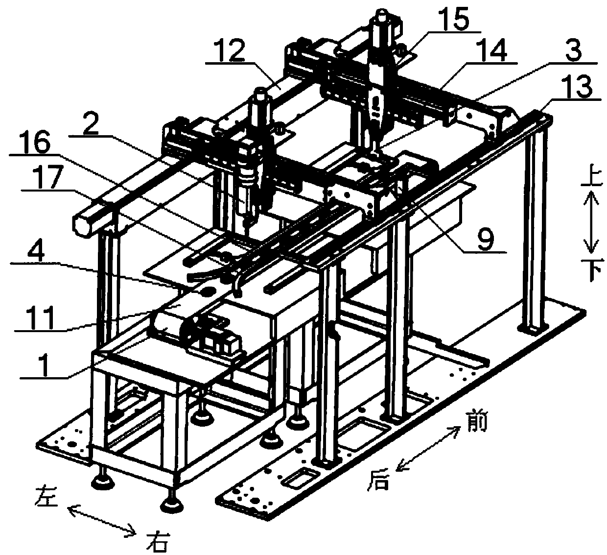
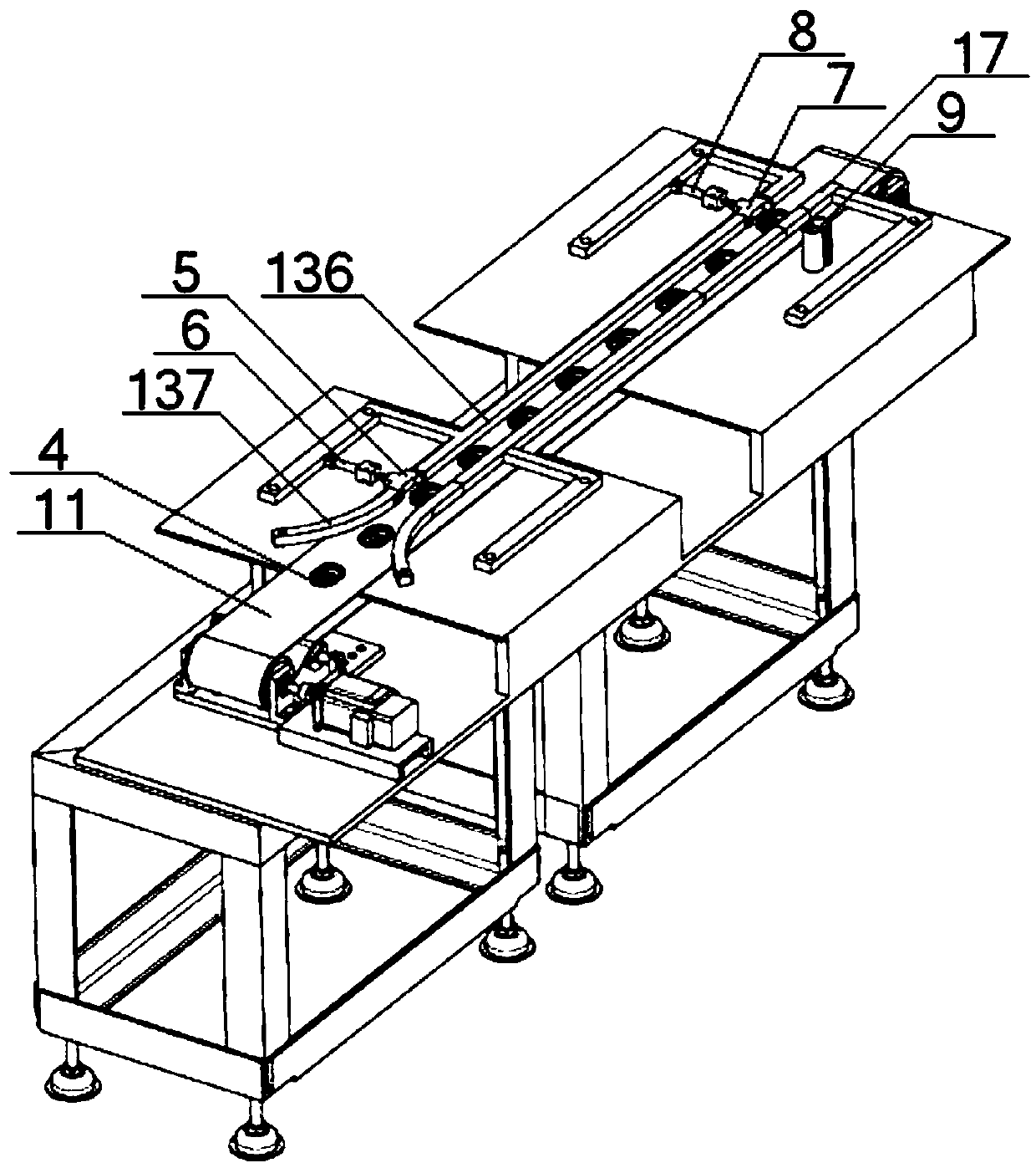
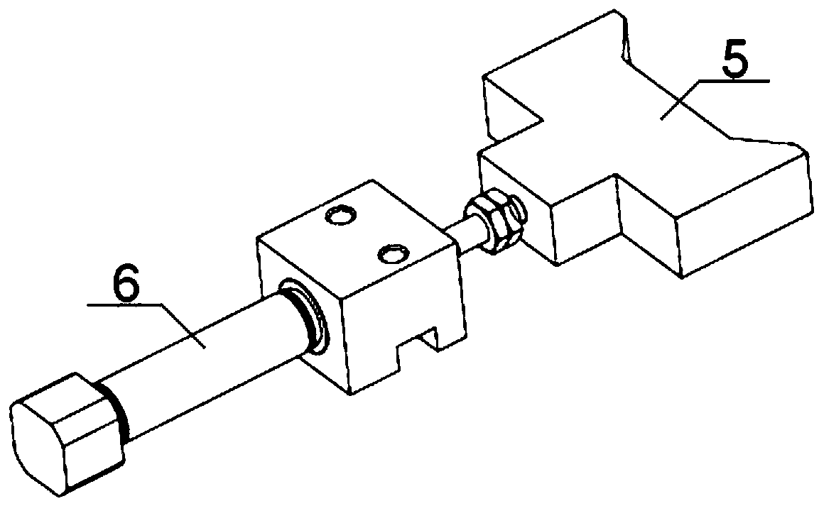
[0064] see Figure 1 to Figure 3 , an ultrasonic probe piezoelectric chip automatic dispensing and mounting machine, comprising a conveying device 1, a glue dispensing machine 2, and a placement machine 3, and the conveying device 1 includes a belt 11 and No. 1 guide rails 12, 2 No. 1 guide rail 13, No. 1 guide rail 12, and No. 2 guide rail 13 are slidably connected with two No. 1 guide posts 14, and both No. 1 guide posts 14 are slidably connected with guide posts 15. The guide columns 14 are perpendicular to each other, and the dispenser 2 and the chip mounter 3 are respectively slidably connected to two guide columns 15; above the belt 11, a No. 1 limit guide rail 16 and a No. Limiting guide rail 17, the position between the No. 1 limiting guide rail 16 and the No. 2 limiting guide rail 17 on the belt 11 is provided with a piezoelectric wafer shell 4, and No. 1 opening slot and No. 2 opening are provided on the No. 1 limiting guide rail 16. No. 1 opening slot is provided w...

Embodiment 2

[0070] Basic content is the same as embodiment 1, the difference is:

[0071] see figure 1 , Figure 4, the dispenser 2 includes the No. 3 pneumatic cylinder 21, injection cylinder 22, and injection head 23 connected in sequence, the No. 3 pneumatic cylinder 21 is connected with the No. 1 guide plate 24, and the No. 1 guide plate 24 is connected with the guide sliding column 15 is slidably connected, the injection barrel 22 is provided with glue; the No. 1 guide plate 24 is connected with an injection head replacement arm 25, and the injection head replacement arm 25 is connected with a positioning block 26 for the injection head 23;

[0072] see figure 1 , Figure 5 , the placement machine 3 includes a No. 2 guide plate 31 and a vertical arm 32, the No. 2 guide plate 31 is slidably connected with the guide column 15, and one end of the vertical arm 32 is connected with the No. 2 guide plate 31, vertically The other end of the arm 32 is connected with an electromagnet 33 t...

Embodiment 3

[0078] Basic content is the same as embodiment 1, the difference is:

[0079] see figure 1 , figure 2 , the No. 1 limit guide rail 16 and the No. 2 limit guide rail 17 all include a straight guide rail 136 and an arc guide rail 137, and the straight guide rail 136 of the No. 1 limit guide rail 16 and the straight guide rail 136 of the No. 2 limit guide rail 17 are arranged in parallel Above the belt 11 , the arc-shaped guide rail 137 of the No. 1 limit guide rail 16 and the arc-shaped guide rail 137 of the No. 2 limit guide rail 17 are arranged above the belt 11 in a figure-eight shape.


PUM


Abstract

Disclosed is an ultrasonic probe piezoelectric wafer automatic glue-dispensing and chip-mounting machine. The ultrasonic probe piezoelectric wafer automatic glue-dispensing and chip-mounting machine comprises a belt, a first guide rail and a second guide rail, wherein the first guide rail and the second guide rail are arranged on the two sides of the belt in parallel; two first guide columns are connected between the first guide rail and the second guide rail in a sliding mode, and the two first guide columns are connected with guiding-sliding columns in a sliding mode; a glue dispensing machine and a chip mounter are connected to the two guiding-sliding columns in a sliding mode respectively; two limiting guide rails are symmetrically arranged above the belt; a piezoelectric wafer shell is arranged on the part, located between the two limiting guide rails, of the belt; two movable blocks are arranged on one limiting guide rail, and the movable blocks are connected with a pneumatic cylinder, and the movable blocks are used for enabling the piezoelectric wafer shell to be abutted against the other limiting guide rail during glue dispensing and chip mounting; a piezoelectric wafer isarranged on the side of the belt; the glue dispensing machine is used for injecting glue liquid into the piezoelectric wafer shell; and the chip mounter is used for attaching the piezoelectric waferto the part, coated with the glue liquid, of the piezoelectric wafer shell. According to the design, the glue dispensing effect is good, the chip mounting effect is good, and the automation degree ishigh.

Description

technical field [0001] The invention relates to the technical field of microelectronic packaging, in particular to an ultrasonic probe piezoelectric wafer automatic dispensing and mounting machine, which is mainly suitable for improving the dispensing effect and mounting effect of piezoelectric wafer installation, and improving the automation of piezoelectric wafer installation degree. Background technique [0002] The Doppler fetal heart rate meter can detect the fetal heartbeat and receive the fetal heart sound with earphones or speakers. It is a fetal heart rate detection device with advanced technology and simple operation. The ultrasonic probe is an important part of the fetal heart rate monitor, which includes a probe shell, an integrated control circuit board set in the probe shell, piezoelectric wafers and signal connection lines respectively set at both ends of the probe shell; the piezoelectric wafer of the ultrasonic probe Undertake the task of transmitting and r...

Claims


Application Information

Patent Timeline
Patent Type & Authority Applications(China)
IPC IPC(8): H01L41/25B05C5/02B05C13/02H10N30/03
CPCB05C5/0208B05C13/02H10N30/03Y02P70/50
Inventor 张成俊李冬冬左小艳游良风刘念叶祥虎陈卓
Owner WUHAN TEXTILE UNIV
Learn More