Rail-road dual-purpose eight-wheel drive traction locomotive floating axle device and using method

A technology for traction locomotives and drive axles, which is used in rail and road dual-use vehicles, motor vehicles, transportation and packaging, etc., can solve the problems of small contact friction area, large turning radius, small friction force, etc. Good traction demand, high traction effect

Pending Publication Date: 2020-08-21
山东智捷专用车制造有限公司
View PDF6 Cites 0 Cited by
  • Summary
  • Abstract
  • Description
  • Claims
  • Application Information

AI Technical Summary

Problems solved by technology

[0003] The driving road surface of dual-purpose traction locomotives for rail and road is often bumpy, multi-slope, slippery, oily, rainy and snowy, and many bends, etc., and the working environment is relatively harsh. When driving on the above-mentioned roads, slipping, being trapped and unable to pass obstacles, and poor climbing ability often occur; in addition, the contact friction area between the two-wheel drive or four-wheel drive dual-purpose tractor and the road / rail is small, and the friction force is small. The ability cannot be fully utilized, which is not conducive to the improvement of traction ability
[0004] In order to solve the above problems, some enterprises have developed rail-road dual-purpose eight-wheel drive traction locomotives. However, due to the large distance between the front and rear axles of the eight-wheel drive traction locomotives, the turning radius is large when turning on the road, and the maneuverability becomes poor.

Method used


Image

  • Rail-road dual-purpose eight-wheel drive traction locomotive floating axle device and using method
  • Rail-road dual-purpose eight-wheel drive traction locomotive floating axle device and using method
  • Rail-road dual-purpose eight-wheel drive traction locomotive floating axle device and using method

Examples


Embodiment 1

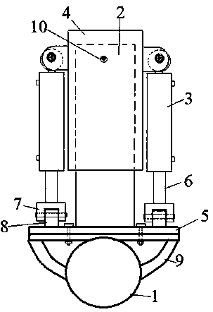
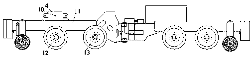
[0019] Attached below figure 1 , 3 , 4 and 5 illustrate the floating bridge device of a dual-purpose eight-wheel-drive traction locomotive of the present invention. The dual-purpose eight-drive traction locomotive is composed of a front frame and a rear frame, and the front frame 11 is provided with two pairs of driving Two pairs of driving wheels are respectively front wheel one 12 and front wheel two 13, and front wheel one 12 is between the guide wheel and front wheel two 13, as attached image 3 shown.

[0020] as attached figure 1 and 2 As shown, the floating bridge device is a lifting device for the drive axle 1 of the front wheel 12, including a fixed plate 5, a lifting arm 2 and a hydraulic cylinder 3, and the fixed plate 5 is located above the two ends of the drive axle 1 and welded with the drive axle 1. The fixed plate 5 is divided into two layers, and the two layers are fixed together with bolts;

[0021] The lower end of the lifting arm 2 is welded to the upp...

Embodiment 2

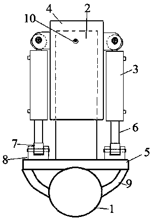
[0027] Attached below figure 2 , 3 and 5 illustrate the floating bridge device of a dual-purpose eight-wheel-drive traction locomotive of the present invention, the dual-purpose eight-drive traction locomotive is made of a front frame and a rear frame, and the front frame 11 is provided with two pairs of drive wheels, Two pairs of drive wheels are respectively front-wheel one 12 and front-wheel two 13, and front-wheel one 12 is between guide wheel and front-wheel two 13, as attached image 3 shown.

[0028] as attached figure 2 As shown, the floating bridge device is a lifting device for the drive axle 1 of the front wheel 12, including a fixed plate 5, a lifting arm 2 and a hydraulic cylinder 3, and the fixed plate 5 is located above the two ends of the drive axle 1 and welded with the drive axle 1. The fixed plate 5 has only one layer;

[0029] The lower end of the lifting arm 2 is welded to the upper surface of the fixed plate 5, and a hydraulic cylinder 3 is arranged...


PUM


Abstract

The invention belongs to the technical field of rail-road dual-purpose traction locomotives, and particularly relates to a rail-road dual-purpose eight-wheel-drive traction locomotive floating axle device and a using method thereof. A front frame of an eight-wheel-drive traction locomotive is provided with two pairs of driving wheels, the two pairs of driving wheels are the first front wheel and the second front wheel correspondingly, and the first front wheel is arranged between a guide wheel and the second front wheel; the floating axle device is a lifting device for a drive axle of the first front wheel and comprises a fixing plate, a lifting arm and a hydraulic cylinder. The rail-road dual-purpose eight-wheel-drive traction locomotive floating axle device has the advantages that the eight-wheel-drive traction locomotive for the rails and the roads gives full play to the advantages that the traction locomotive has high traction force on the steel rails, has high trafficability on wet and slippery/rugged roads and still has considerable maneuverability when running on the roads, the advantages are improved, disadvantages are avoided, and traction requirements are better met.

Description

technical field [0001] The patent of the present invention belongs to the technical field of dual-purpose traction locomotives for rail and road, and specifically relates to a floating bridge device for a dual-purpose eight-drive traction locomotive for rail and road and a method for using it. Background technique [0002] Rail-road dual-purpose tractor series products are widely used in special railway lines such as electric power, metallurgy, chemical industry, building materials, ports, logistics and small freight yards, as well as production and construction of railway stations, locomotive depots, bullet train depots, subways and engineering bureaus The unit replaces the traditional traction method in the past, and the brand-new design concept has amazed some users, and the value for money is excellent. [0003] The driving road surface of dual-purpose traction locomotives for rail and road is often bumpy, multi-slope, slippery, oily, rainy and snowy, and many bends, etc...

Claims


Application Information

Patent Timeline
Patent Type & Authority Applications(China)
IPC IPC(8): B62D61/12B60F1/02
CPCB62D61/12B60F1/02
Inventor 岳公华岳浩然曹平先岳亮朱绍华赵克卿董元珂
Owner 山东智捷专用车制造有限公司
Why Eureka
Try Eureka