
Cross arm structure for combined power tower and use method

A power tower and combined technology, applied in the field of cross arm structures for combined power towers, can solve the problems of poor wind and snow resistance, easy accumulation of snow on the cross arms, and inability to cope with harsh environments, so as to reduce impact and reduce The effect of influencing and avoiding burden

Active Publication Date: 2020-08-21
SHENGLI OILFIELD HENGYUAN ELECTRIC
View PDF6 Cites 4 Cited by
  • Summary
  • Abstract
  • Description
  • Claims
  • Application Information

AI Technical Summary

Problems solved by technology

The vertical reinforcement plate and the horizontal reinforcement plate are integral and direct structures. The U-shaped bolt mounting holes are located on the vertical reinforcement plate surface, the pole clamping holes, bracket installation holes and clamping ears are located on the horizontal reinforcement plate surface, and the fastening holes are located on the horizontal reinforcement plate surface. Located on the clamping lugs; although it can prevent birds from nesting and improve a certain strength, the overall ability to resist wind and snow is poor and cannot cope with harsh environments. easy to accumulate snow

Method used


Image

  • Cross arm structure for combined power tower and use method
  • Cross arm structure for combined power tower and use method
  • Cross arm structure for combined power tower and use method

Examples


Embodiment Construction

[0029] The following will clearly and completely describe the technical solutions in the embodiments of the present invention with reference to the accompanying drawings in the embodiments of the present invention. Obviously, the described embodiments are only some, not all, embodiments of the present invention.

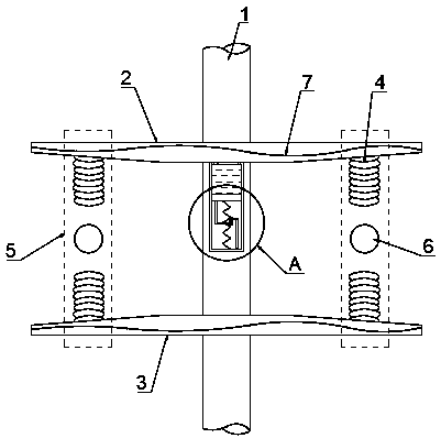
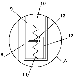
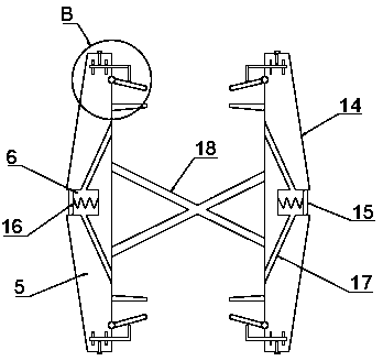
[0030] refer to Figure 1-5 , a combined cross-arm structure for power poles and towers, including an upper cross-arm 2 and a lower cross-arm 3 arranged on a pole and tower 1, the lower side walls of the upper cross-arm 2 and the upper side walls of the lower cross-arm 3 are fixed with suspension type insulator 4, the middle part of the upper cross arm 2 and the lower cross arm 3 is provided with a mounting opening 24, and the outer wall of the upper cross arm 2 and the lower cross arm 3 is provided with two openings communicating with the installation port 24. The middle part of the bearer 2 and the lower cross arm 3 is also provided with a threaded port communicati...


PUM


Abstract

The invention discloses a cross arm structure for a combined power tower. The cross arm structure comprises an upper cross arm and a lower cross arm which are arranged on the tower, suspension insulators are fixed to the lower side wall of the upper cross arm and the upper side wall of the lower cross arm correspondingly, and mounting openings are formed in the middle of the upper cross arm and the middle of the lower cross arm correspondingly; two through openings communicating with the interiors of the mounting openings are formed in the outer walls of the upper cross arm and the lower crossarm, threaded openings communicating with the interiors of the mounting openings are further formed in the middles of the upper cross arm and the lower cross arm, a U-shaped plate is jointly insertedbetween the two through openings, and fastening bolts matched with the threaded openings are in threaded connection with the U-shaped plate; and the two sides of the upper cross arm and the two sidesof the lower cross arm are each provided with a baffle located on the outer sides of the suspension insulators. By means of the cross arm structure, the baffles are arranged to shield wind power, theinfluence of air flow on the suspension insulators is reduced, the overall stability is guaranteed, meanwhile, connection between a heating wire and a power source is triggered for heating when the air temperature is low, accumulated snow accumulation is avoided, and the overall wind and snow resistance is improved.

Description

technical field [0001] The invention relates to the technical field of pole and tower cross arms, in particular to a combined power pole and tower cross arm structure and a use method. Background technique [0002] The angle iron fixed horizontally on the top of the utility pole has a porcelain vase on it, which is used to support the overhead wire. The function of the cross arm: The cross arm is an important part of the tower. Its function is to install insulators and fittings to support the wires and lightning conductors and keep them at a certain safe distance according to regulations. [0003] Authorized notification number CN205422124U discloses a reinforced structure wire crossarm, which belongs to the technical field of electric equipment, and consists of a vertical reinforcement plate, a U-bolt mounting hole, a horizontal reinforcement plate, a pole clamping hole, a bracket mounting hole, a clamping lug and Composition of fastening holes. The vertical reinforcement...

Claims


Application Information

Patent Timeline
IPC IPC(8): E04H12/24H05B3/06
CPCE04H12/24H05B3/06
Inventor 张胜军
Owner SHENGLI OILFIELD HENGYUAN ELECTRIC
Learn More