A temperature monitoring method of combined electric appliance based on fiber grating sensor

A combination of electrical appliances and optical fiber grating technology, applied in the direction of physical/chemical changes in thermometers, thermometers, thermometer parts, etc., can solve problems such as aging joints, melting deformation, insulation performance reduction, etc., and achieve the effect of improving sensitivity

Active Publication Date: 2021-07-23
SHANDONG ELECTRICAL ENG & EQUIP GRP +1
View PDF9 Cites 0 Cited by
  • Summary
  • Abstract
  • Description
  • Claims
  • Application Information

AI Technical Summary

Problems solved by technology

According to the statistical analysis of combined electrical faults in recent years, it is found that the abnormal temperature rise of conductor joints mainly occurs at the bus joints, branch bus joints and disconnector joints. The overheating of combined electrical joints may cause insulation aging and may even cause joints to melt and deform, which in turn leads to insulation performance. reduce, causing major power grid accidents such as short circuits
At present, non-online monitoring methods such as handheld thermal imaging cameras are commonly used to regularly detect the bus temperature of combined electrical appliances, which have high resolution and temperature measurement accuracy, but are expensive, and the effectiveness of the test is easily affected by factors such as the environment, and it is difficult Realize the integrated integration of online monitoring system

Method used


Image

  • A temperature monitoring method of combined electric appliance based on fiber grating sensor
  • A temperature monitoring method of combined electric appliance based on fiber grating sensor
  • A temperature monitoring method of combined electric appliance based on fiber grating sensor

Examples


Embodiment 1

[0022] This embodiment discloses a method for monitoring the temperature of an optical fiber grating for a combined electrical appliance. The method includes the following steps:

[0023] S01), pre-stretching the temperature-measuring fiber grating and encapsulating it in the base material for sensitization to form a fiber grating sensor. After the encapsulation is completed, the residual stress is eliminated by changing the temperature. The base material has a high thermal expansion coefficient and stable thermophysical properties. Fiber compatibility is high;

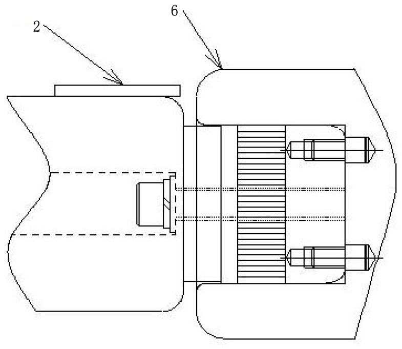
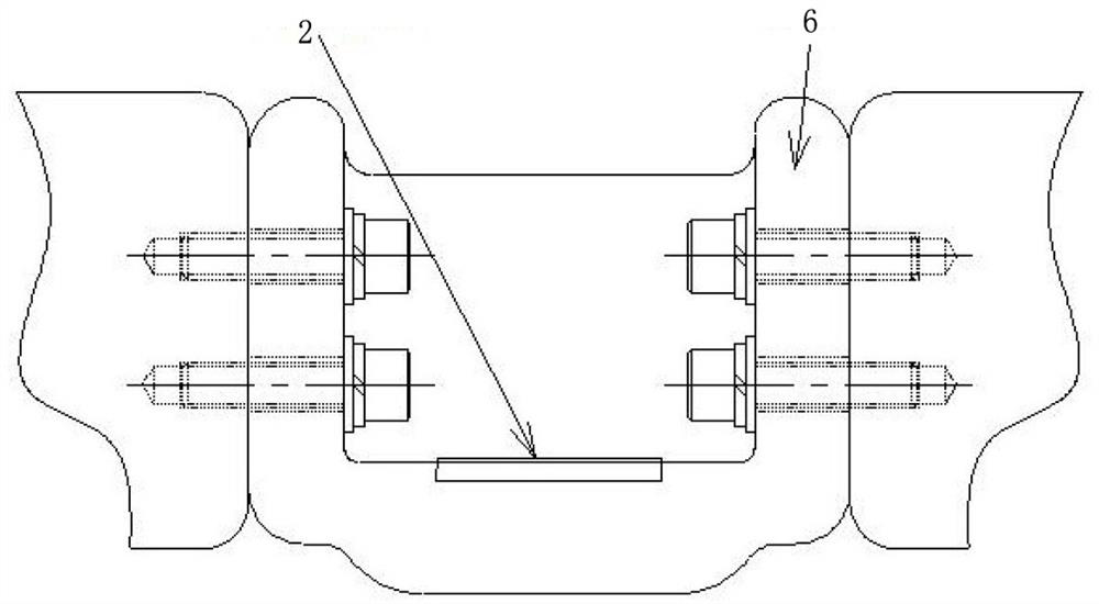
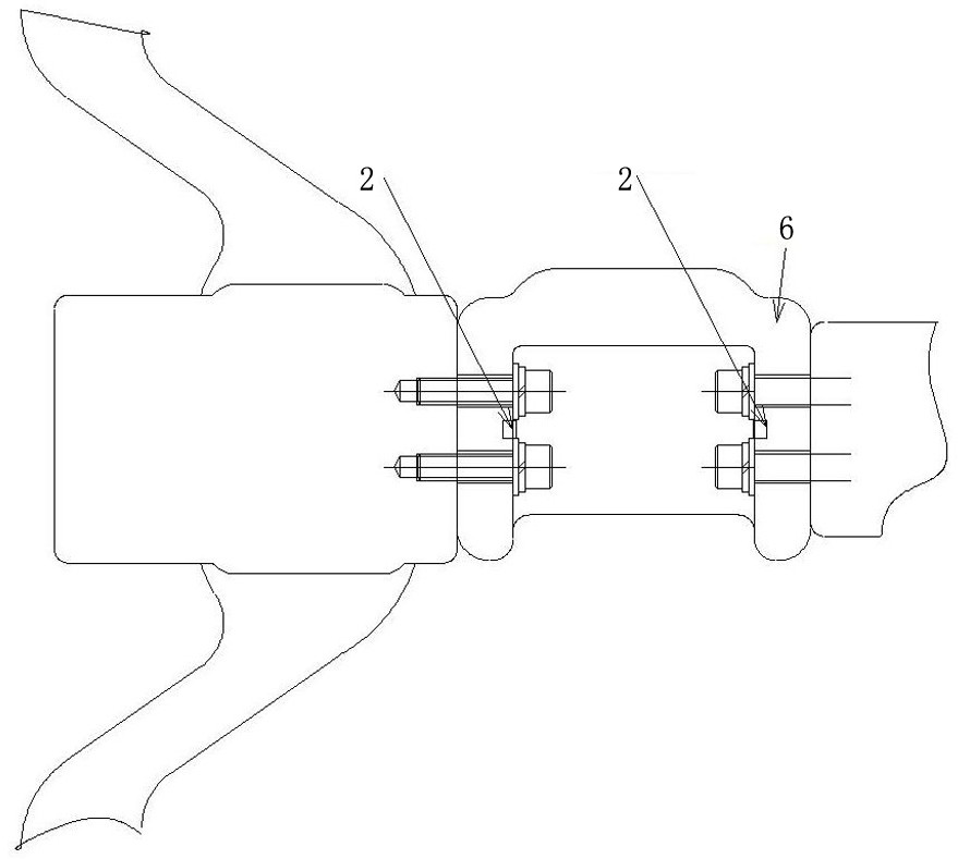
[0024] In this embodiment, the optical fiber grating sensor 2 is used to collect the temperature information of the internal joints of the combined electrical appliance. The thermal expansion effect and the thermo-optic effect of the optical fiber grating sensor will occur due to the change of the external environment temperature. The grating period change caused by the thermal expansion effect is: ΔΛ= α·Λ·ΔT, Λ is th...


PUM

PropertyMeasurementUnit
Sensitivityaaaaaaaaaa

Abstract

The invention discloses a method for monitoring the temperature of a combined electrical appliance based on a fiber grating sensor. This method combines the environmental characteristics of SF6 to study a new packaging method to improve the sensitivity and accuracy of the sensor, and then without changing the original structure, sealing performance, and insulation characteristics of the combined electrical appliance. On the basis, the sensor is fixed inside the combined electrical appliance by pasting, inlaying, and bundling, and the signal transmission is realized through the signal connection plate, and finally an online temperature monitoring system integrating the temperature measurement system and the combined electrical appliance is realized. Compared with the prior art, the present invention no longer indirectly deduces the internal temperature through the external measurement of the combined electrical appliance, but directly develops new materials, new processes and installation means, and after testing the feasibility of internal installation and measurement, the sensor is installed at the measured point. Realize the direct measurement of the internal joint temperature of the combined electrical appliance, and monitor the operating status of the combined electrical equipment on-line in real time.

Description

technical field [0001] The invention relates to the technical field of temperature measurement of substation combined electrical equipment, in particular to a method for monitoring the temperature of combined electrical equipment based on an optical fiber grating sensor. Background technique [0002] Gas-insulated combined electrical appliances (referred to as combined electrical appliances) are widely used in power systems. It is a combination of primary equipment other than transformers that is enclosed in a metal cylinder filled with a certain pressure of SF6 insulating gas. According to the statistical analysis of combined electrical faults in recent years, it is found that the abnormal temperature rise of conductor joints mainly occurs at the bus joints, branch bus joints and disconnector joints. The overheating of combined electrical joints may cause insulation aging and may even cause joints to melt and deform, which in turn leads to insulation performance. Reduced, c...

Claims


Application Information

Patent Timeline
Patent Type & Authority Patents(China)
IPC IPC(8): G01K11/3206G01K1/14G01K1/02G01K1/022G01K1/143
CPCG01K11/3206G01K1/14G01K1/02
Inventor 史存伟王新刚傅春明闫冠峰李军李凤民吕腾飞张猛时培征付志达栾兰张文赋
Owner SHANDONG ELECTRICAL ENG & EQUIP GRP
Why Eureka
Try Eureka