Multi-angle adjustable reflector device for dental clinical

A clinical, multi-angle technology, applied in the clinical field of oral cavity, can solve the problems of impact, fixed and non-adjustable mirror angles, etc.

Inactive Publication Date: 2020-08-25
殷晓萍
View PDF0 Cites 1 Cited by
  • Summary
  • Abstract
  • Description
  • Claims
  • Application Information

AI Technical Summary

Problems solved by technology

[0004] The purpose of the present invention is to solve the shortcomings of the existing oral mirror handles that the length of the handle and the angle of the mirror are fixed and non-adjustable, which affects the doctor's judgment of the situation in the patient's oral cavity, and proposes a multi-angle oral mirror for clinical use. adjustable mirror assembly

Method used


Image

  • Multi-angle adjustable reflector device for dental clinical
  • Multi-angle adjustable reflector device for dental clinical
  • Multi-angle adjustable reflector device for dental clinical

Examples


Embodiment 1

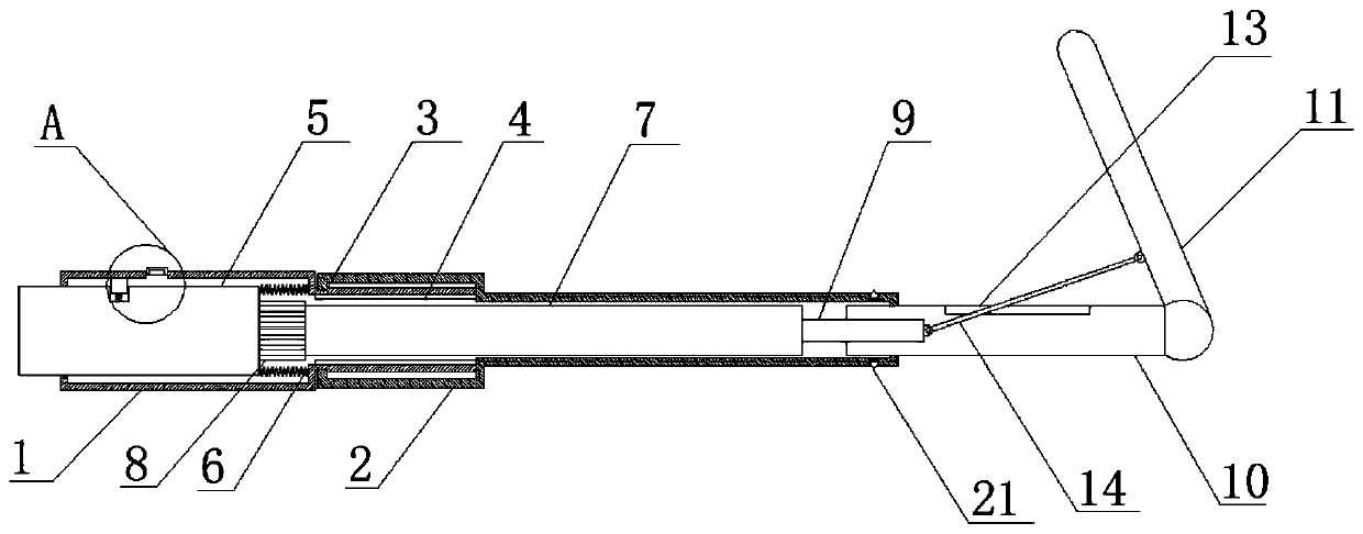
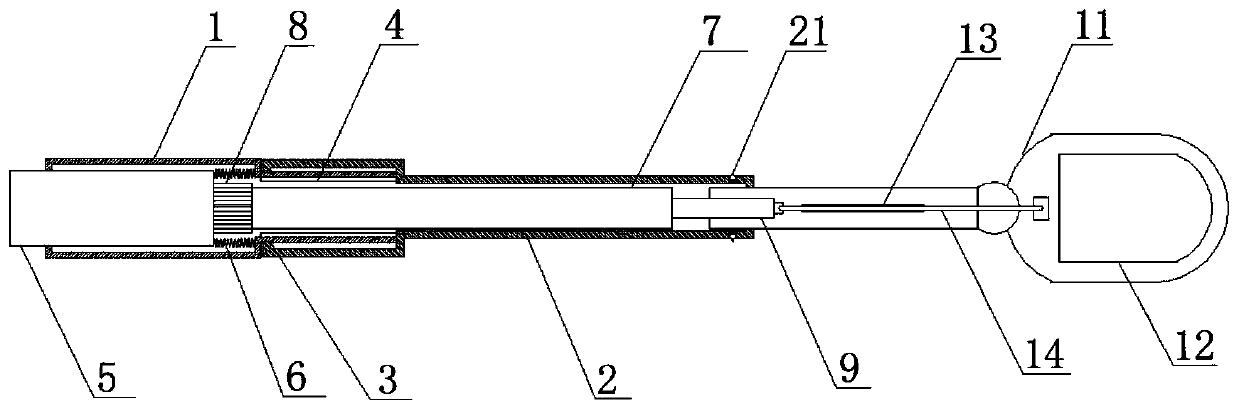
[0020] refer to Figure 1-3 , a multi-angle adjustable mirror device for oral cavity clinical use, comprising a first housing 1, an annular chute 3 is opened on the surface of the first housing 1, and a second housing 2 is sleeved on the first housing 1 , the second housing 2 is matched with the annular chute 3, the inner wall of the first housing 1 is fixedly provided with an annular rack 4, one end of the first housing 1 is provided with a circular hole, and a first Push rod 5, one end of the first push rod 5 is fixedly connected with one end of the first spring 6, the other end of the first spring 6 is fixedly connected with one side inner wall of the first housing 1, the other end of the first push rod 5 Extending to the outside of the first housing 1, a second push rod 7 is slidably arranged in the second housing 2, and one end surface of the second push rod 7 is fixedly sleeved with a gear 8 and fixedly connected to the first push rod 5, The gear 8 is matched with the r...

Embodiment 2

[0026] refer to Figure 1-3 , a multi-angle adjustable mirror device for oral cavity clinical use, comprising a first housing 1, an annular chute 3 is opened on the surface of the first housing 1, and a second housing 2 is sleeved on the first housing 1 , the second housing 2 is matched with the annular chute 3, the inner wall of the first housing 1 is fixedly provided with an annular rack 4, one end of the first housing 1 is provided with a circular hole, and a first Push rod 5, one end of the first push rod 5 is fixedly welded with one end of the first spring 6, the other end of the first spring 6 is fixedly welded on one side inner wall of the first housing 1, the other end of the first push rod 5 Extending to the outside of the first housing 1, the second housing 2 is slidably provided with a second push rod 7, one end surface of the second push rod 7 is fixedly sleeved with a gear 8 and fixedly welded on the first push rod 5, The gear 8 is matched with the ring rack 4, t...


PUM


Abstract

The invention belongs to the technical field of dental clinical, and particularly relates to a multi-angle adjustable reflector device for dental clinical. The problem that the adjustment of a doctoron the situation of an oral cavity of a patient is affected due to the fact that the length of a handle of an existing oral reflector and the angle of the reflector are both fixed and non-adjustable is solved. According to the scheme, the multi-angle adjustable reflector device includes a first housing, an annular sliding groove is formed in the surface of the first housing, the first housing is sleeved with a second housing, the second housing is in cooperation with the annular sliding groove, an annular rack is fixedly arranged on the inner wall of the first housing, a circular hole is formed in one end of the first housing, and a first push rod is slidably connected in the circular hole. A rotation rod and a mirror frame are driven to rotate by adopting the first housing to rotate a second push rod and a third push rod to realize the multi-angle adjustment of the reflector, and meanwhile, a clamping block on the first push rod and a first groove squeeze to open a button battery switch when being matched so as to turn on a circuit of an LED light to illuminate oral cavity of the patient.

Description

technical field [0001] The invention relates to the field of clinical oral cavity technology, in particular to a multi-angle adjustable reflector device for clinical oral cavity. Background technique [0002] The oral cavity is the beginning of the digestive system. Its front wall is the upper and lower lips, the side wall is the cheek, the upper wall is the palate, and the lower wall is the floor of the mouth. The pharynx communicates with the pharynx. The oral cavity can be divided into the oral vestibule and the proper oral cavity. The former is located in the gap between the upper and lower lips and cheeks and the upper and lower dental arches and gums, and the latter is located in the space surrounded by the upper and lower dental arches and gums. It is the palate, and the bottom (floor of the mouth) is composed of mucous membrane, muscle and skin. In clinical oral medicine, a mirror is often used to observe the patient's oral cavity. [0003] The length of the handle...

Claims


Application Information

Patent Timeline
Patent Type & Authority Applications(China)
IPC IPC(8): A61B1/247A61B1/06A61B1/00
CPCA61B1/00025A61B1/00183A61B1/0684A61B1/247
Inventor 殷晓萍董霞
Owner 殷晓萍
Why Eureka
Try Eureka