Oil-water separation device and machine tool water tank with same

A technology of oil-water separation device and machine tool water tank, which is applied in the field of machine tool water tank and oil-water separation device, and can solve the problems of low separation efficiency of oil-water separation device

Pending Publication Date: 2020-08-25
ZHUHAI GREE INTELLIGENT EQUIP CO LTD +1
View PDF2 Cites 0 Cited by
  • Summary
  • Abstract
  • Description
  • Claims
  • Application Information

AI Technical Summary

Problems solved by technology

[0004] The main purpose of the present invention is to provide an oil-water separation device and a machine tool water tank with it, so as to solve the problem of low separation efficiency of the oil-water separation device in the prior art

Method used


Image

  • Oil-water separation device and machine tool water tank with same
  • Oil-water separation device and machine tool water tank with same
  • Oil-water separation device and machine tool water tank with same

Examples


Embodiment Construction

[0028] It should be noted that, in the case of no conflict, the embodiments in the present application and the features in the embodiments can be combined with each other. The present invention will be described in detail below with reference to the accompanying drawings and examples.

[0029] It should be noted that, unless otherwise specified, all technical and scientific terms used in this application have the same meaning as commonly understood by those of ordinary skill in the art to which this application belongs.

[0030] In the present invention, in the absence of a contrary statement, the used orientation words such as "up and down" usually refer to the direction shown in the drawings, or refer to the vertical, vertical or gravity direction Similarly, for the convenience of understanding and description, "left and right" usually refer to the left and right shown in the drawings; The words are not used to limit the invention.

[0031] In order to solve the problem of...


PUM


Abstract

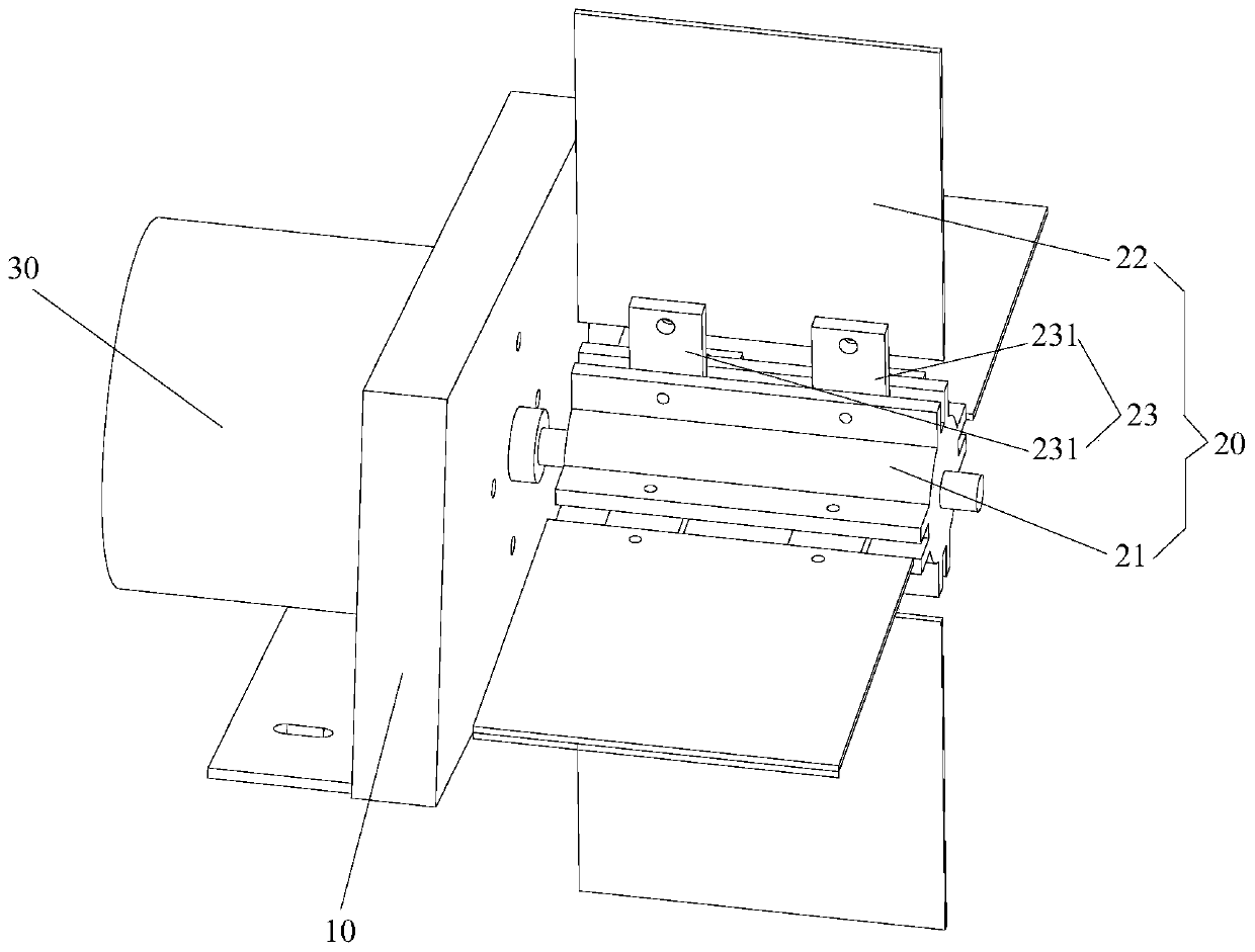
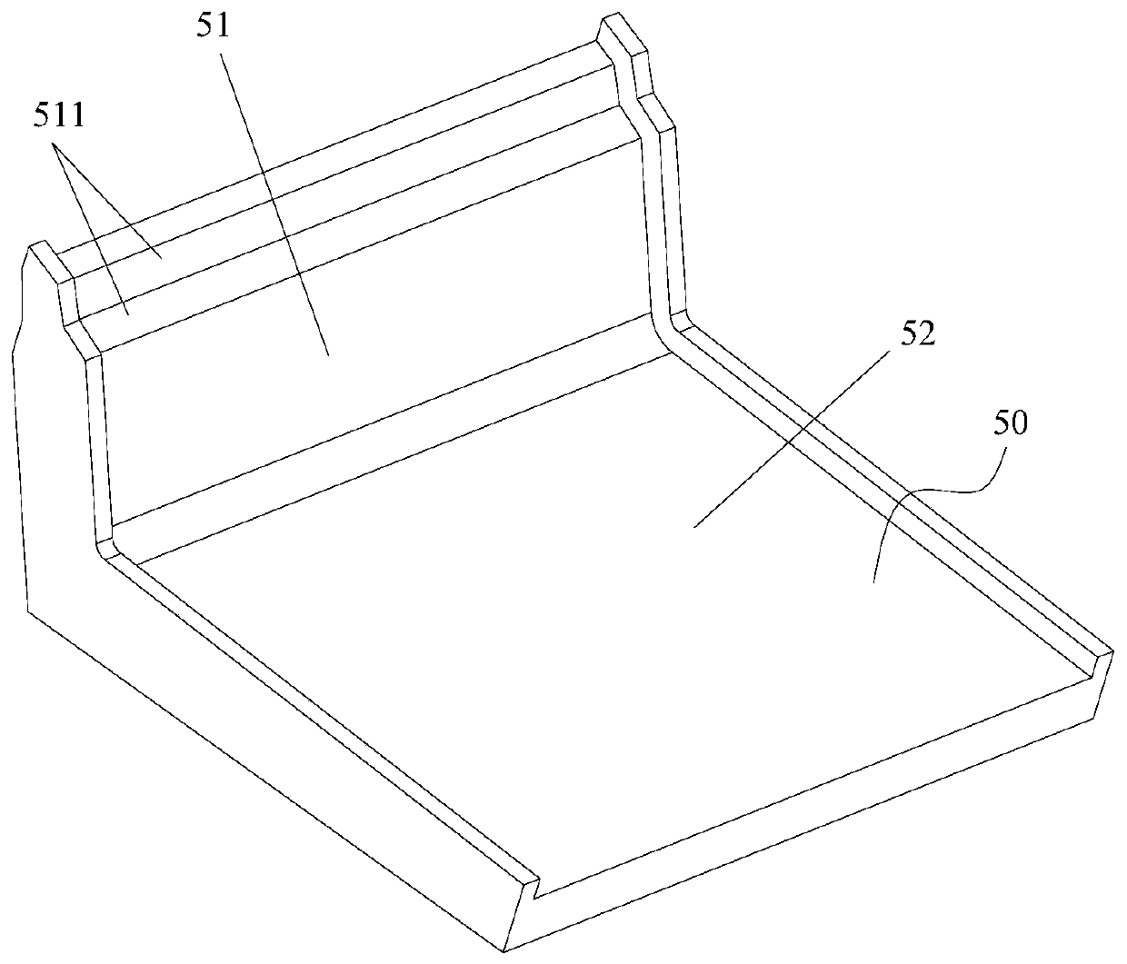
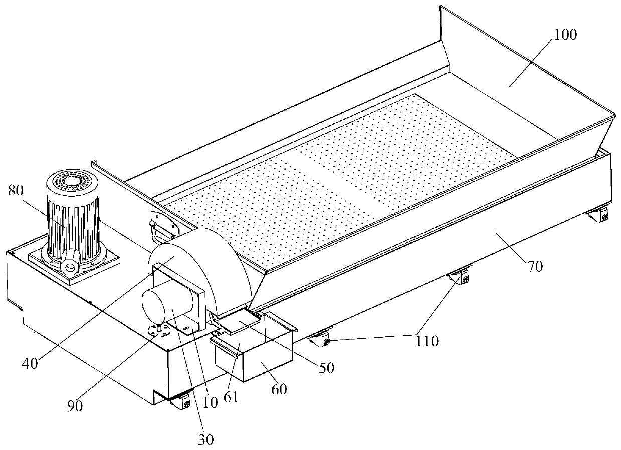
The invention provides an oil-water separation device and a machine tool water tank with the same. The oil-water separation device comprises a seat body; a separation structure which comprises a rotating part and a plurality of blades arranged on the rotating part, the blades being arranged at intervals in the circumferential direction of the rotating part and used for stirring an oil-water mixture to be separated; a driving structure which is arranged on the seat body, and is in driving connection with the rotating part to drive the rotating part to drive the blades to rotate; wherein at least part of each blade is made of a lipophilic material. The oil-water separation device effectively solves the problem of low separation efficiency of oil-water separation devices in the prior art.

Description

technical field [0001] The invention relates to the technical field of oil-water separation, in particular to an oil-water separation device and a machine tool water tank provided with it. Background technique [0002] At present, CNC machine tools are widely used in the field of cutting processing and are one of the important equipment for metal cutting processing. Specifically, during the operation of the CNC machine tool, cutting fluid is usually used. The cutting fluid can not only reduce friction and reduce temperature, but also reduce metal strength. However, after the CNC machine tool is finished processing, the cutting fluid is directly discharged into the environment, which will cause water resources and soil pollution. [0003] In the prior art, in order to improve the above problems, the oil and water in the cutting fluid are usually separated, and after the separation is completed, they are treated separately and will not be directly discharged into the environm...

Claims


Application Information

Patent Timeline
IPC IPC(8): B01D17/022B03C1/30
CPCB01D17/0202B03C1/30
Inventor 郭雷雷杨建新林茂康
Owner ZHUHAI GREE INTELLIGENT EQUIP CO LTD
Why Eureka
Try Eureka