
A Sand Cleaning Process for Automobile Flywheel Castings

A processing technology and casting technology, which is applied in the field of sand cleaning processing technology for automobile flywheel castings, can solve the problems of high labor intensity, mixing of waste sand in the air, environmental pollution, etc., and achieve the effect of improving work efficiency and reducing labor intensity.

Active Publication Date: 2021-12-10
新沂市棋盘工业集中区建设发展有限公司
View PDF11 Cites 0 Cited by
  • Summary
  • Abstract
  • Description
  • Claims
  • Application Information

AI Technical Summary

Problems solved by technology

[0003] As a kind of auto parts, the flywheel is a disc-shaped part with a large moment of inertia. It functions as an energy storage. For a four-stroke engine, work is done once every four piston strokes, that is, only the work stroke does work. The three strokes of exhaust, intake and compression all consume work, so the torque output by the crankshaft changes periodically, and the crankshaft speed is also unstable. In order to improve this situation, a flywheel is installed at the rear end of the crankshaft; existing The flywheel is mainly produced by casting. Since the side of the flywheel is gear-shaped and the surface is uneven, a large amount of raw sand will often be mixed in the casting. Therefore, the finished flywheel needs to be sand-cleaned.
[0004] Under the existing technical conditions, the solution to the problem of sand removal is: the method of manual knocking and washing: this work method is inefficient, the sand removal is not thorough, and the labor intensity is high; the method of shaking the sand is used: the method The sand cleaning effect of the working method is relatively high, but if the source is too large, it is easy to mix the waste sand in the air, causing serious environmental pollution.

Method used


Image

  • A Sand Cleaning Process for Automobile Flywheel Castings
  • A Sand Cleaning Process for Automobile Flywheel Castings
  • A Sand Cleaning Process for Automobile Flywheel Castings

Examples


Embodiment Construction

[0031] Embodiments of the present invention will be described below with reference to the drawings. In the process, in order to ensure the clarity and convenience of illustration, we may exaggerate the width of the lines or the size of the constituent elements in the diagram.

[0032] In addition, the following terms are defined based on the functions in the present invention, and may be different according to the user's or operator's intention or practice. Therefore, these terms are defined based on the entire content of this specification.

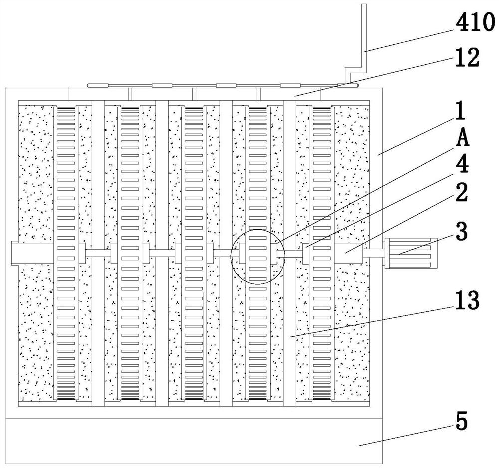
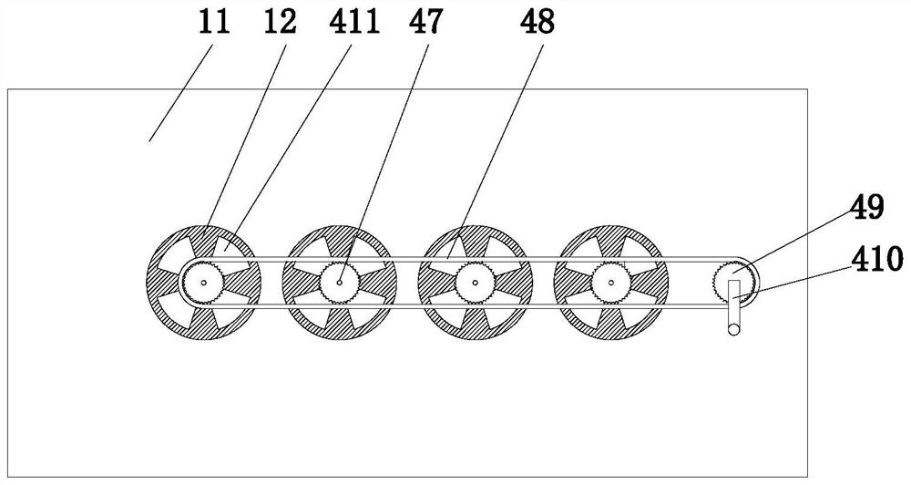
[0033] Such as Figure 1 to Figure 7 As shown, a sand cleaning treatment process for automobile flywheel castings is mainly completed by a sand cleaning treatment equipment for automobile flywheel castings. The sand cleaning treatment equipment for automobile flywheel castings includes a system body 1, a fixed block 2, and a motor 3 , a clamping mechanism 4 and a dust accumulation mechanism 5, the inner walls of the left and right side...


PUM


Abstract

The invention provides a sand cleaning treatment process for automobile flywheel castings, which is mainly completed by a sand cleaning treatment equipment for automobile flywheel castings. The sand cleaning treatment equipment for automobile flywheel castings includes a system body, a fixed block, a motor, a clamp The fixed mechanism and the dust accumulation mechanism, the inner walls of the left and right sides of the system body are connected with fixed blocks through rotating shafts, the motor is located on the right outer surface of the system body, the fixed block on the right side and the system motor The rotors are connected by rotating shafts. The inner cavity of the system body is provided with multiple sets of clamping mechanisms, and the dust accumulation mechanism is located directly below the system body; If it is not thorough, the labor intensity is high and the seismic source is too large, it is easy to mix the waste sand in the air, causing serious environmental pollution.

Description

technical field [0001] The invention relates to the technical field of casting workpiece processing, in particular to a sand cleaning process for automobile flywheel castings. Background technique [0002] Casting is a metal thermal processing process. Casting is a method of casting liquid metal into a casting cavity that is suitable for the shape of the part, and after it is cooled and solidified, a method of obtaining parts or blanks; Low, high process flexibility, complex shapes and large castings can be obtained, which occupy a large proportion in mechanical manufacturing; [0003] As a kind of auto parts, the flywheel is a disc-shaped part with a large moment of inertia. It functions as an energy storage. For a four-stroke engine, work is done once every four piston strokes, that is, only the work stroke does work. The three strokes of exhaust, intake and compression all consume work, so the torque output by the crankshaft changes periodically, and the crankshaft speed...

Claims


Application Information

Patent Timeline
Patent Type & Authority Patents(China)
IPC IPC(8): B22D31/00
CPCB22D31/002
Inventor 俞镔
Owner 新沂市棋盘工业集中区建设发展有限公司
Learn More