
Abrasive jet machining equipment

A processing equipment and abrasive technology, applied in metal processing equipment, abrasive jet machine tools, abrasives, etc., can solve problems such as inability to recycle, unfavorable equipment use, and reduced practical reliability, so as to improve sealing efficiency and processing efficiency. Facilitate the recovery of abrasives and the effect of dust sealing

Active Publication Date: 2020-08-25
邹平丰泰新材料科技有限公司
View PDF8 Cites 1 Cited by
  • Summary
  • Abstract
  • Description
  • Claims
  • Application Information

AI Technical Summary

Problems solved by technology

[0002] There are many shortcomings in the existing equipment, such as abrasive jet processing, because of the inability to form a completely closed structure, the jetted abrasives are easy to fly out to the external space after jetting, and cannot be recovered, and due to the use of jet machining There is no way to shield the dust generated when the parts are polished, which will be extremely harmful to the environment where the equipment is located in the long run, and due to the existence of the above shortcomings, it is impossible to recycle the abrasive when the equipment is working , which makes the equipment work less efficiently and increase the cost of use due to the excessive wear of abrasives during use, which is not only not conducive to the continuous use of the equipment, but also reduces the practical reliability of the equipment in actual work.

Method used


Image

  • Abrasive jet machining equipment
  • Abrasive jet machining equipment
  • Abrasive jet machining equipment

Examples


Embodiment Construction

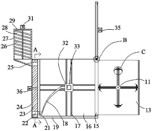
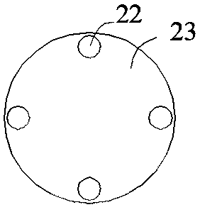
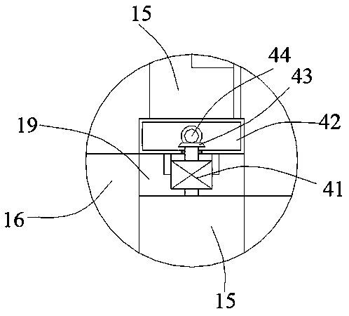
[0029] Such as Figure 1-Figure 8 As shown, the present invention is described in detail. For the convenience of description, the orientations mentioned below are now stipulated as follows: figure 1 The up, down, left, right, front and back directions of the projection relationship itself are consistent. A kind of abrasive jet processing equipment of the present invention includes a middle box 19, an open inner cavity 16 is arranged in the middle box 19, and one side of the inner cavity 16 is provided with The sliding inner cavity 24 located in the middle box body 19, one side of the sliding inner cavity 24 is communicated with a squeeze-in cavity 25, and one side of the squeeze-in cavity 25 is provided with a The feeding device, the sliding inner chamber 24 is provided with a conveying device capable of transporting the abrasive in the feeding device to the inner chamber 16, and the middle box 19 is provided with two rotating side plates 15 for rotation, so The rotating side p...


PUM


Abstract

The invention discloses abrasive jet machining equipment. The abrasive jet machining equipment comprises a middle box, an open inner cavity is formed in the middle box, a sliding inner cavity locatedin the middle box is formed in one side of the inner cavity, a squeezing cavity is formed in one side of the sliding inner cavity in a communicating mode, a feeding device used for feeding into the sliding cavity is arranged on one side of the squeezing cavity, a conveying device capable of conveying abrasive in the feeding device into the inner cavity is arranged in the sliding inner cavity, tworotating side plates are rotatably arranged in the middle box, and the rotating side plates correspondingly close the side surface and the top surface of the inner cavity. The abrasive jet machining equipment is simple in structure, the mode capable of simultaneously closing and opening the machining working space is adopted, clamping can be carried out according to tools of the upper side and theside surfaces; and meanwhile, abrasive jet grinding machining is carried out on the tools in multiple directions, the sealing efficiency and machining efficiency of the equipment are effectively improved, and abrasive recovery and dust close are convenient.

Description

technical field [0001] The invention relates to the technical field of abrasive jet processing equipment, in particular to abrasive jet processing equipment. Background technique [0002] There are many shortcomings in the existing equipment, such as the abrasive jet processing cannot form a completely closed structure, so the jetted abrasives are easy to fly out to the external space after jetting, and cannot be recovered, and due to the use of jet machining There is no way to shield the dust generated when the parts are polished, which will be extremely harmful to the environment where the equipment is located in the long run, and due to the existence of the above shortcomings, the abrasive cannot be recycled when the equipment is working , which makes the equipment work less efficiently and increase the cost of use due to excessive abrasive wear when the equipment is in use, which is not only unfavorable for the continuous use of the equipment, but also reduces the practi...

Claims


Application Information

Patent Timeline
IPC IPC(8): B24C3/04B24C7/00B24C9/00
CPCB24C3/04B24C7/0046B24C9/00B24C9/003B24C9/006
Inventor 胡月明
Owner 邹平丰泰新材料科技有限公司
Learn More