
Gear selecting and shifting positioning mechanism for gear selecting and shifting actuator

A technology of positioning mechanism and gear selection and shifting, which is applied in the direction of instruments, controlled components, mechanical equipment, etc., and can solve the problems of shortening the service life of various parts, sliding friction of gear selection door parts, and easy scratches in gear selection and shifting, etc. Achieve the effects of reducing product failure rate, improving stability and consistency, and reducing abnormal noise when selecting and shifting gears

Pending Publication Date: 2020-08-25
ZHEJIANG KEBODA IND
View PDF0 Cites 1 Cited by
  • Summary
  • Abstract
  • Description
  • Claims
  • Application Information

AI Technical Summary

Problems solved by technology

This is unacceptable for dimensionally critical gearbox designs
[0004] In addition, the thin sheet structure adopted in the above scheme has sharp edges, which is prone to scratches when selecting and shifting gears, and sliding friction is easily formed between the gear selecting door parts, and the friction resistance is large, which easily leads to gear shifting failures and shortens the life of each component. service life, and bring abnormal noise when selecting and shifting gears

Method used


Image

  • Gear selecting and shifting positioning mechanism for gear selecting and shifting actuator
  • Gear selecting and shifting positioning mechanism for gear selecting and shifting actuator
  • Gear selecting and shifting positioning mechanism for gear selecting and shifting actuator

Examples


Embodiment Construction

[0020] The present invention will be described in detail below in conjunction with the accompanying drawings and specific embodiments.

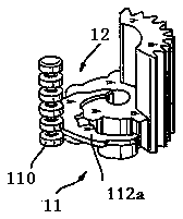
[0021] Please refer to Figure 4 to Figure 10 . A gear selection positioning mechanism for a gear selection actuator according to an embodiment of the present invention includes a gear selection shaft 1 , a gear selection gate 2 , a limit pin 3 , a gear 4 and a limit pin installation part.

[0022] The gear selection shaft 1 is rotatably arranged on the housing 5 of the gear selection actuator. In this embodiment, the first motor 61 drives the gear selection shaft 1 to move axially through a first transmission mechanism (not shown in the figure). The dial finger 8 is fixedly installed on the gear selection shaft 1, and can move and rotate together with the gear selection shaft 1, and then act on the gear shift track (not shown in the figure) of the gear selection actuator to realize gear selection.

[0023] The gear selection door 2 is fix...


PUM


Abstract

The invention relates to a gear selecting and shifting positioning mechanism for a gear selecting and shifting actuator. The gear selecting and shifting positioning mechanism comprises a gear selecting and shifting shaft, a gear selecting door, a limiting pin and a limiting pin mounting part. The limiting pin is arranged on the limiting pin mounting part. The gear selecting door is fixedly arranged on the gear selecting and shifting shaft, and the outer surface of the gear selecting door is provided with an open slot and a plurality of limiting grooves; and the plurality of limiting grooves are arranged at intervals in the axial direction parallel to the axis of the gear selecting and shifting shaft, and the open slot extends in the axial direction parallel to the axis of the gear selecting and shifting shaft and is vertically intersected with the plurality of limiting grooves. When the gear selecting door moves axially, the limiting pin extending into the open slot is enabled to be selectively aligned with one limiting groove; and when the gear selecting door rotates in the circumferential direction, the limiting pin extending into the open slot is enabled to enter the limiting groove aligned with the limiting pin, or the limiting pin extending into the limiting groove is enabled to enter the open slot. According to the gear selecting and shifting positioning mechanism in theinvention, the strength and rigidity of the product are increased without increasing the volume of the product, and the friction force in the gear selecting and shifting process can be reduced.

Description

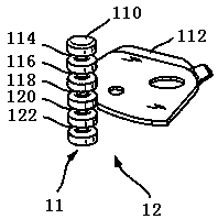
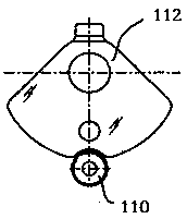
technical field [0001] The invention relates to the gear shifting technology of an automobile transmission. Background technique [0002] The gear selection actuator of the automobile gearbox includes a gear selection shaft and a gear selection door. The gear selection shaft can move axially to select a gear, and can rotate to achieve a gear change. The gear selection gate is used to ensure the positioning of the gear shift. accuracy. figure 1 with figure 2 A three-dimensional structure schematic diagram and a top view schematic diagram of the existing gear selection door are respectively shown. Wherein, the gear selection door 12 includes a first gear selection door part 110 and a second gear selection door part 112, the first gear selection door part 110 is fixedly connected with the housing of the actuator, and the second gear selection door part 112 is connected to the gear selection door part 112. The gear selector shaft, the second selector gate member 112 is movab...

Claims


Application Information

Patent Timeline
IPC IPC(8): F16H61/32F16H63/30F16H63/32
CPCF16H61/32F16H63/30F16H63/32F16H2063/3076F16H2063/324
Inventor 李战训刘钊
Owner ZHEJIANG KEBODA IND
Learn More