Photoacoustic spectrometry oil and gas monitoring system

A monitoring system and a technology of photoacoustic spectroscopy, applied in the field of detection, can solve problems such as the inability to monitor multiple gases at the same time, and achieve the effect of improving practicability

Pending Publication Date: 2020-08-25
HUBEI INFOTECH SYST TECH CO LTD
View PDF0 Cites 2 Cited by
  • Summary
  • Abstract
  • Description
  • Claims
  • Application Information

AI Technical Summary

Problems solved by technology

[0004] The present invention aims at the technical problem that in the existing photoacoustic spectroscopy oil and gas monitoring system in the prior art, generally only one substance can be monitored, and the monitoring of multiple gases cannot be realized at the same time. The present invention provides a photoacoustic spectroscopy oil and gas monitoring system

Method used


Image

  • Photoacoustic spectrometry oil and gas monitoring system
  • Photoacoustic spectrometry oil and gas monitoring system
  • Photoacoustic spectrometry oil and gas monitoring system

Examples


Embodiment Construction

[0047] The principles and features of the present invention are described below in conjunction with the accompanying drawings, and the examples given are only used to explain the present invention, and are not intended to limit the scope of the present invention.

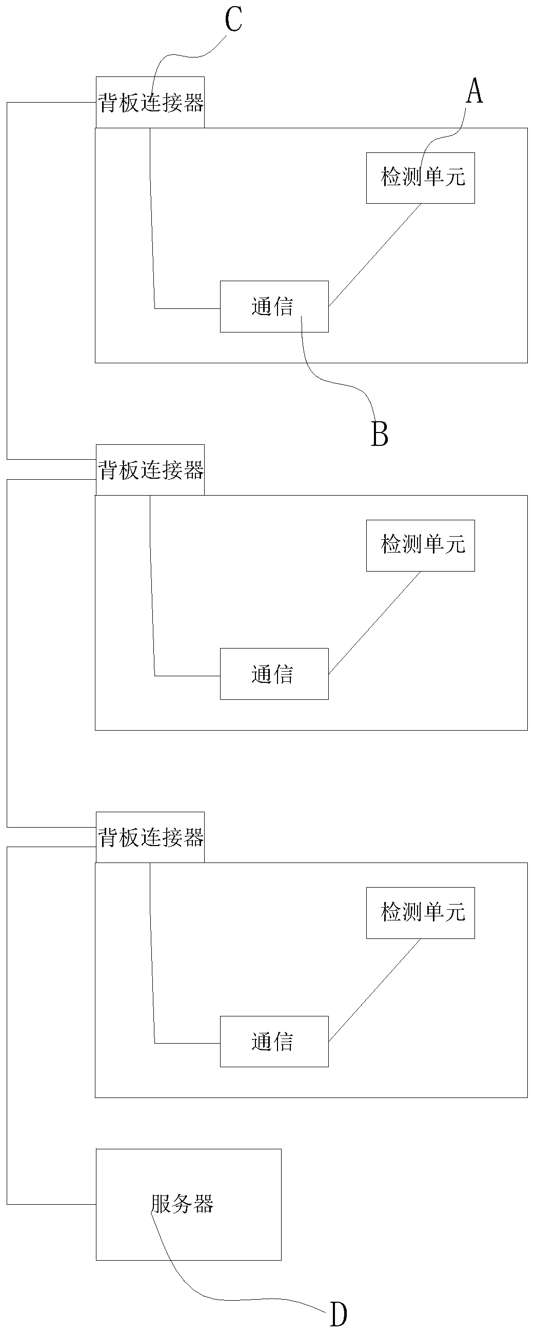
[0048] refer to Figure 1 to Figure 3 As shown, a photoacoustic spectrum oil and gas monitoring system includes: at least two oil and gas monitoring units A, each oil and gas monitoring unit A can monitor a gas independently, each oil and gas monitoring unit A is connected to a communication circuit B, and the communication circuit B For the intersection of signals, the communication circuit B is connected to the backplane connector C, and the adjacent backplane connectors C are connected to each other, and a bridge for mutual communication is built through the backplane connector C, and any one of the backplane connectors C is connected to There is a server D, and the signal is synthesized through the server D to r...


PUM


Abstract

The invention discloses a photoacoustic spectrometry oil and gas monitoring system. The system comprises at least two oil gas monitoring units, and each oil gas monitoring unit is connected with a communication circuit; the communication circuit is connected with a backboard connector; adjacent backboard connectors are connected with each other; any one of the backboard connectors is connected with a server; according to the system disclosed in the invention, the plurality of oil and gas monitoring units are separately connected with one communication circuit; the communication circuit is connected with one backboard connector, the backboard connectors are connected with one another, signals of the oil and gas monitoring units can intersect with one another and then are sent to the server,monitored signals are integrated, and therefore monitoring of various substances is achieved; practicability of the photoacoustic spectrometry oil and gas monitoring system is greatly improved.

Description

technical field [0001] The invention relates to the technical field of detection, in particular to a photoacoustic spectrum oil and gas monitoring system. Background technique [0002] The existing oil and gas monitoring system mainly places substances in airtight containers. The substances will be excited after absorbing light of a specific wavelength, and the excited substances will return to the initial state through radiative transition or non-radiative transition. This process will generate heat. ; If the wavelength of the absorbed light changes periodically, the pressure fluctuations in the container are also periodic; since the frequency of the modulated light is generally in the audio frequency range, the pressure fluctuations become sound waves; and then sensed by the acoustic sensor The electrical signal obtained by synchronously amplifying the acoustic signal perceived by the acoustic sensor is an optical signal. If the photoacoustic signal is recorded as a functi...

Claims


Application Information

Patent Timeline
Patent Type & Authority Applications(China)
IPC IPC(8): G01N21/17G01N21/01
CPCG01N21/01G01N21/1702G01N2021/1704G01N2201/12G01N2201/126
Inventor 李玉林易国华许立群罗浩夏历李俊逸
Owner HUBEI INFOTECH SYST TECH CO LTD
Why Eureka
Try Eureka