Battery module

A battery module and cell technology, applied in battery pack components, secondary batteries, circuits, etc., can solve the problems of unstable battery pack safety performance, and achieve the effect of improving battery safety and stability.

Active Publication Date: 2020-08-25
CHONGQING JINKANG POWER NEW ENERGY CO LTD
View PDF10 Cites 23 Cited by
  • Summary
  • Abstract
  • Description
  • Claims
  • Application Information

AI Technical Summary

Problems solved by technology

[0005] In view of this, the embodiment of the present invention provides a battery module to solve the problem of unstable safety performance of the battery pack in the prior art

Method used


Image

  • Battery module
  • Battery module
  • Battery module

Examples


Embodiment 1

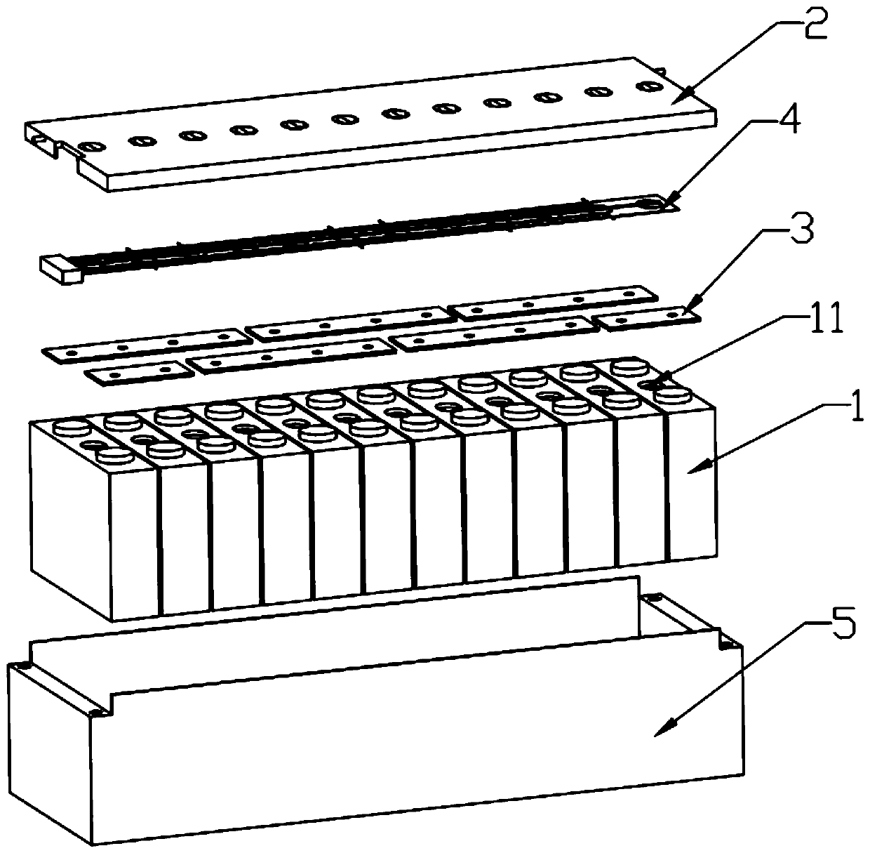
[0029] refer to figure 1 and figure 2 , the battery module involved in this application includes a battery cell 1 , a conductive medium 3 and a fire extinguishing device 2 . The cells 1 are rectangular parallelepiped cells or cylindrical cells, and each cell 1 is provided with an exhaust valve 11 on the top, and the cells 1 are arranged in sequence. The conductive medium 3 is arranged on the top of the cell 1 to electrically connect the cell 1 . Optionally, the conductive medium 3 is electrically connected to the cell 1 in series or in parallel. The fire extinguishing device 2 is set corresponding to the exhaust valve 11, refer to figure 1 , The fire extinguishing device 2 is arranged above the battery cell 1, and when thermal runaway occurs, the fire extinguishing treatment is performed on the battery cell 1.

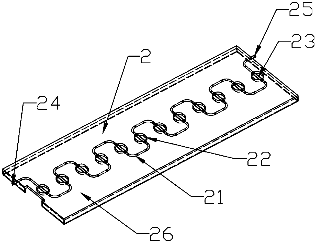
[0030] Depend on figure 2 As shown, the fire extinguishing device 2 includes a flow channel 21 , a first heat conduction hole 22 , a liquid discharge device 23 ,...

Embodiment 2

[0042] The second embodiment is a further improvement made on the basis of the first embodiment, and the specific difference between the second embodiment and the first embodiment is the structure of the liquid discharge device 23 .

[0043] refer to Figure 6 and Figure 7 , the liquid discharge device 23 includes a tubular body 231 and a liquid storage cavity 232 disposed in the middle section of the tubular body 231 . In the direction perpendicular to the flow of the coolant, the sectional area of ​​the liquid storage cavity 232 is larger than that of the tubular body 231 . This setting can store more cooling fluid on the one hand, to ensure that when the liquid discharge device 23 is fused by the gas discharged from the exhaust valve 11, there will be a sufficient amount of cooling fluid to spray the thermally runaway battery cell; on the other hand, it can The contact area between the liquid discharge device 23 and the gas discharged from the exhaust valve 11 is increas...


PUM

PropertyMeasurementUnit
melting pointaaaaaaaaaa

Abstract

The invention discloses a battery module, which comprises a plurality of battery cells arranged side by side and a fire extinguishing device, wherein the battery cells are provided with exhaust valves; the fire extinguishing device comprises a liquid discharging device used for circulation of cooling fluid, the liquid discharging device comprises a normal state and a liquid discharging state, andwhen the liquid discharging device is in the liquid discharging state, the cooling fluid flows out of the liquid discharging device to cool the battery cell; a first heat conduction hole is formed inthe fire extinguishing device, and the first heat conduction hole is arranged opposite to the exhaust valve to form an exhaust channel for guiding gas exhausted from the exhaust valve; and the liquiddischarging device is arranged in the first heat conduction hole. The exhaust channel is formed in the outer side of the exhaust valve of the battery cell and is used for guiding gas exhausted by theexhaust valve, so that uncontrollable fusing position of the gas due to deviation of an exhaust path is avoided, and the safety of the battery is improved.

Description

technical field [0001] The invention relates to the technical field of new energy vehicle power battery safety, in particular to a battery module. Background technique [0002] With the development of new energy vehicles, the power battery has gained more room for development and growth, and people's demand for the mileage of the power battery has become higher and higher, which requires increasing the energy density of the power battery itself. With the improvement of the energy density of the battery cell, it is becoming more and more difficult to guarantee the thermal stability of the battery, because there are more and more accidents of fire and explosion caused by thermal runaway. Therefore, the thermal safety of new energy vehicles is becoming more and more important. When a battery cell catches fire or thermal runaway occurs, how to avoid triggering other battery cells to catch fire and spread, eventually causing the vehicle to catch fire, causing casualties and prop...

Claims


Application Information

Patent Timeline
Patent Type & Authority Applications(China)
IPC IPC(8): H01M2/12H01M10/613H01M10/625H01M10/6567A62C99/00A62C37/00A62C3/16
CPCH01M10/613H01M10/625H01M10/6567A62C3/16A62C37/00A62C99/0009A62C99/0072H01M50/383H01M50/394Y02E60/10
Inventor 郭盛昌王爽赵建雄
Owner CHONGQING JINKANG POWER NEW ENERGY CO LTD
Why Eureka
Try Eureka